
| Welcome to our how-to section! This and several other slot car tutorials, tips and technical articles can be found on our forums. Please use the following link to add comments or discuss this material: https://austinslotcarclub.com/forums/topic/using-a-pressurized-mold-to-resin-cast-an-f1-wing/. |
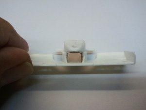
Our club was planning on a race series using F1 slot cars. It was expected that we would need replacement body parts not readily available, particularly front wings. I decided to tackle resin casting the front wings. Studying the complex shape of the wing, I tried to figure out how to make a mold. The first thing to decide is where the parting line of the two halves of the mold would be. It was clear that the upper and lower surfaces of the main wing element would be the two surfaces of the mold, with the parting line along the wing edges. The parting line would then follow along the edges of the rest of the wing. The second thing I noticed was that the central wing supports could use some beefing up.
 |
 |
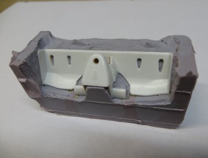
I packed modeling clay along the inside surfaces of the wing supports, sculpting it with an Exacto knife and a small spatula. I left the clay thicker at the rear and thin at the front.

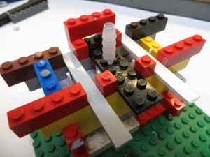
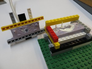
Although the upper and lower surfaces of the wing would divide the mold, the wing did not have to sit horizontally in the mold. Angling the wing would make adding the fill and vent tubes easier. Once again I used Legos for the mold, with the bottom of the wing sitting at a 45 degree angle and clay filling what was actually the top of the wing. I packed the clay and scraped it back to the edges of the wing elements.
The clay I added to the inside of the wing supports is a little misleading in the photo. The rest of the clay in the photo will be removed and replaced with RTV mold material for the second part of the mold, while the clay inside the supports will remain when the second part of the mold is poured.
Every mold requires at least one fill tube and every high point will require a vent tube to keep air bubbles from forming. I superglued styrene rod for two larger fill tubes and four smaller vent tubes.
I have added a couple of keyways to the clay that will help locate the two halves of the mold. The roughness of the clay is not an issue as it will form the mating surfaces of the two parts of the RTV mold.

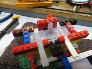
To make the pouring of the resin easier, I joined the two fill tubes with a couple of pieces of balsa to make a fill reservoir. I ended up shortening the fill tubes and lowering the balsa.

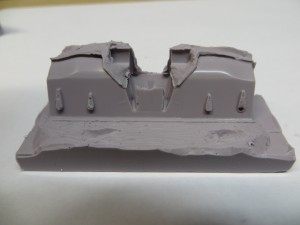
Once again I used PolyTek EasyFlo 60 RTV compound, mixing it 50/50 in a plastic cup and pouring into the mold, until the level of the RTV just came up to the top of the balsa. The first time, the RTV that I had on hand was old and didn’t flow well, leaving voids in the mold. I put everything back together and poured new RTV into the mold. The color variations in the mold reflect the two pours; the two pours bonded well. This is what the first part of the mold looked like when I took it out of the Lego form. You can just see the four vent tubes sticking up and the balsa where the fill reservoir will be.
After cleaning all the clay (except for the support-thickening clay inside) I placed the original wing back in the poured RTV. This assembly is turned upside down from the previous photo.
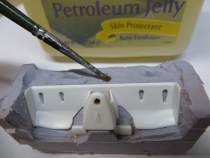
To avoid having the second half of the mold stick to the first, I painted petroleum jelly on the exposed surfaces of the RTV. I have tried various liquid mold release products but have not had much luck with them.

With the Lego mold re-formed around the first mold section, this photo shows the vibrator that Ary Barbosa provided. A slot car wheel is glued to a spare motor shaft, slightly off-center. The motor is attached to a Lego with Shoo-Goo. When this motor is connected to a power supply, it vibrates, helping eliminate air bubbles in the mold.
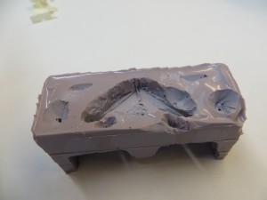
The second half of the mold is shown here. This was the bottom in the first pour and was all clay in that first RTV pour. It will be turned upside down as it is here and will be the bottom again.
Using a sprue cutter, I enlarged the fill reservoir and cone-shaped areas around the vent tubes at the top of the first pour. When I pour the resin, I will keep pouring until resin appears in all the vents.

Using Polytek EasyFlo 60 super low viscosity polyurethane resin, I poured equal amounts into two mixing cups and poured it into the two-part mold. The result was close but had incomplete areas. After some thought, I decided to try making a pressurized mold. To accomplish this I would make a third RTV layer on top, covering the fill reservoir, with a tube sticking up that I could blow into, forcing the resin to fill the mold below.

I filled the fill reservoir with clay and stuck a hose barb fitting into it, and put styrene extension rods in the vent tubes.
I raised the walls of the Lego mold and put Lego strips across the top of the walls, the center piece with a hole for the hose barb fitting. I originally thought that these Lego pieces would remain separate from the third RTV layer, but the third RTV pour locked them together with the RTV
After coating the RTV with petroleum jelly, I poured more RTV into the form, some of it flowing over the Lego pieces across the mold. As it turned out this third layer stays together pretty well and can be removed from the original Lego form as a unit. After removing some of the unnecessary Lego pieces from this third section and attaching a vinyl tube to the hose barb fitting it was ready to try. With the third section unattached, I mixed the resin and poured it into the fill reservoir and then connected the third layer to the top and blew gently into the tube until i saw resin coming out of all the vent tubes. If someone wished to try this and did not want to blow into the tube, a blown-up balloon could be slipped over the tube and air released into the tube.

This was the result of this final pour


Using a sprue cutter I clipped off the resin vent tubes that had poked up through the third mold section and clipped away at the remaining resin in the fill reservoir until I could pull the second part of the mold off the lower part.
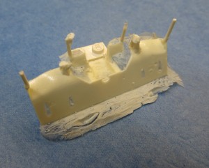
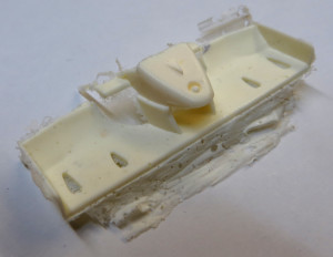
This is the final wing as it was pulled from the mold. The fill reservoir resin had been attached to the top of the thick posts and the remainder of the vent tubes are visible. These will all be clipped off and sanded down. One result of using a pressurized mold in this manner is that there may be more flash as the resin is forced between the parts of the mold by the pressure, but this is easily removed.
Obviously, this was a complex pour and I hope that the photos and text are clear enough, but this same technique of using a removable top part of the mold with an air tube can be used on many molds that otherwise may not achieve a complete pour.
Good Luck!