Home › Forums › Club Races › Racing Calendar, Classes & Regulations › Upgrading the 2015 Formula GP car with the new SVQ-Slot chassis
- This topic has 11 replies, 4 voices, and was last updated 9 years, 8 months ago by
 BarkingSpyder.
-
AuthorPosts
-
December 29, 2015 at 2:38 AM #8661
The new Formula GP chassis for 2016 from SVQ-Slot has arrived; got four units in and another five have been ordered, which should arrive in late January.
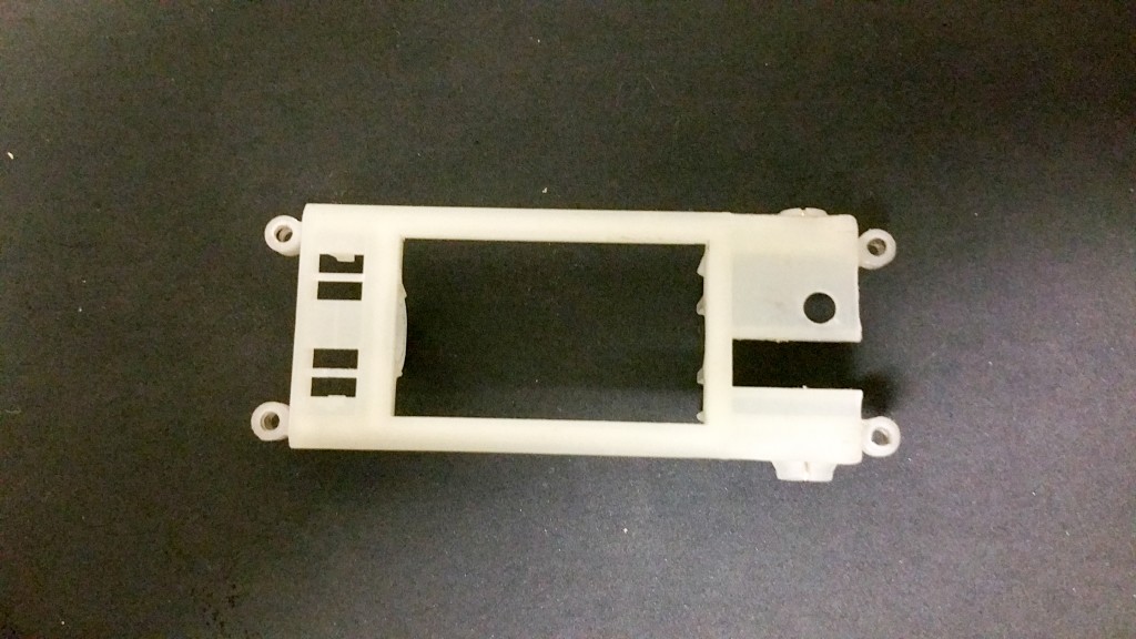
We will be racing the SVQ-Slot chassis with the non-offset version of Slot.it’s boxer motor-pod (CH48) – which is black … and I’m using the white on the pictures … the white is not legal … get the black; ok?
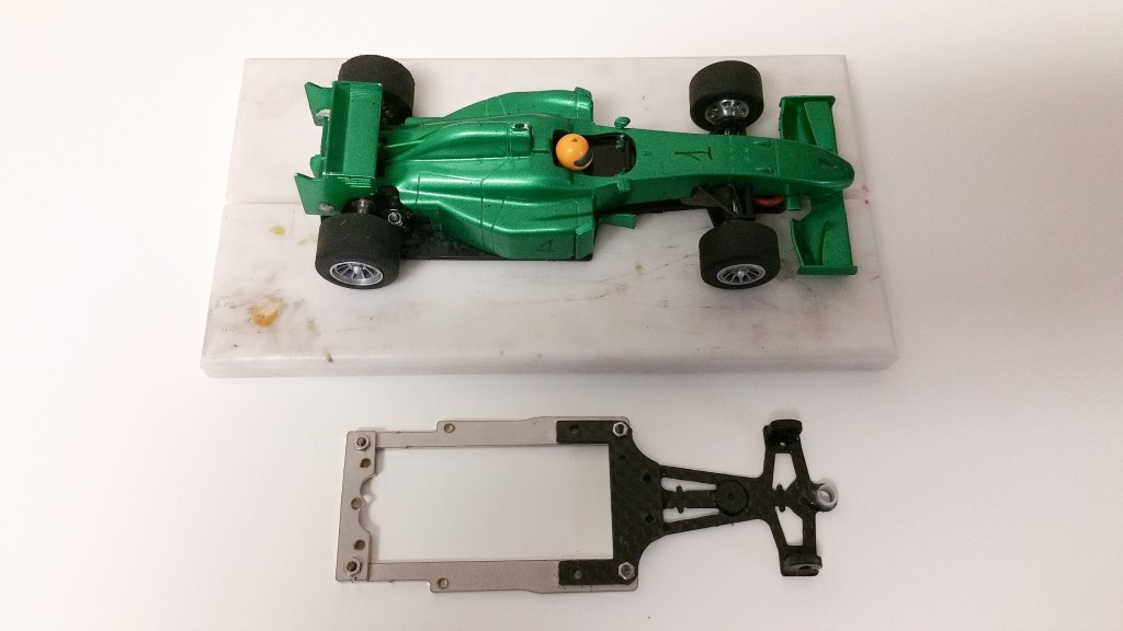
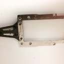
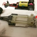
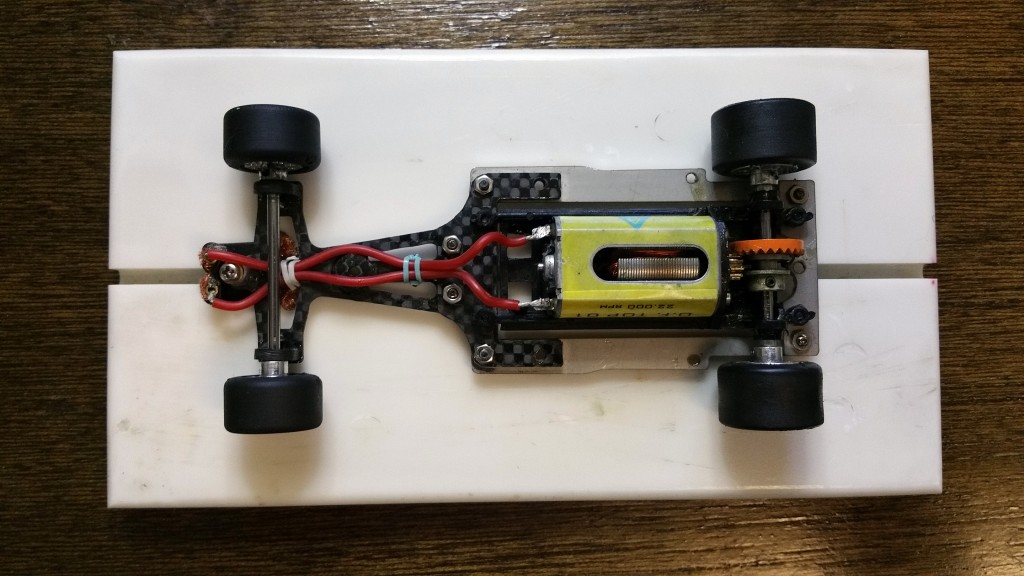
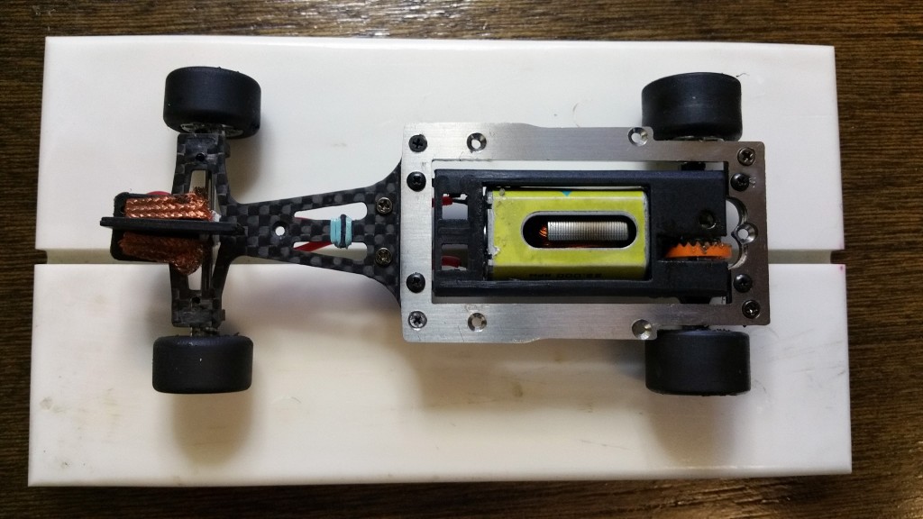
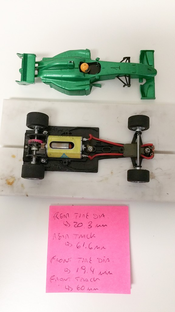
So, in this first picture you will see the car I raced in 2015 and the new chassis bellow it. I just wanted to get some measurements before proceeding.
Car weight at 76.34 grams with a distribution of approximately 57% rear and 43% front. I did have a small ballast installed in the front as you will see a fell pictures bellow.
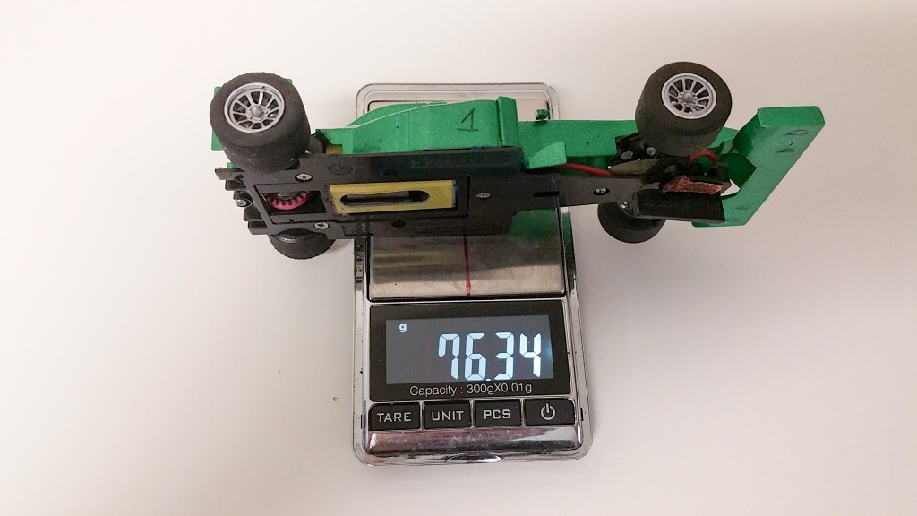
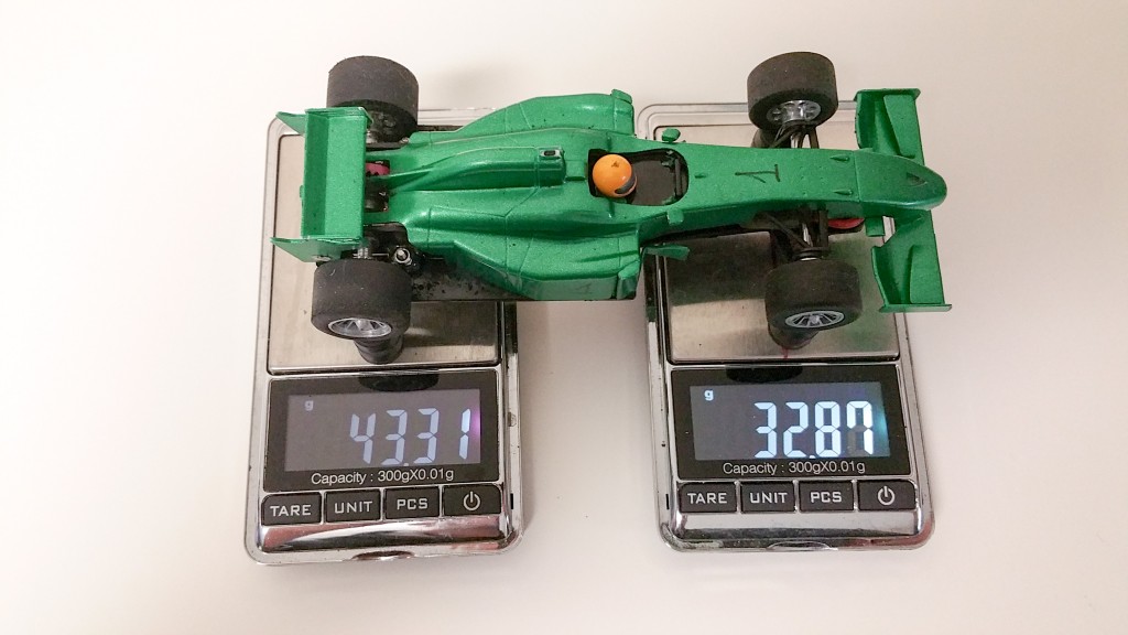
Here you can see the ballast (which weighted exactly 5 grams) and a few measurements; again, just something to compare to when I’m done with the transplant.
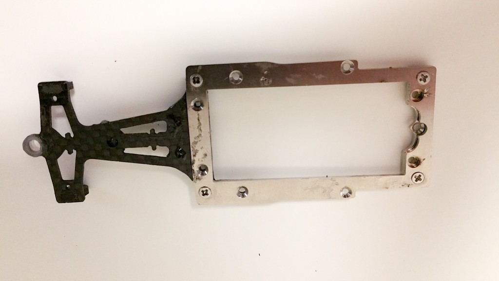
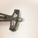
The new chassis came from the manufacturer as you see in the picture bellow. There was some glue residue but nothing that couldn’t be fixed.
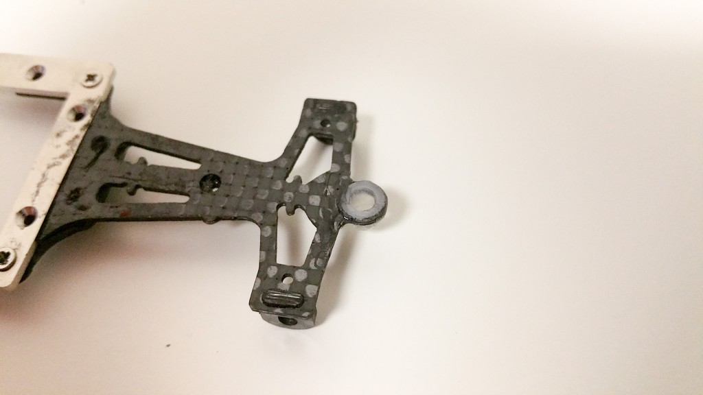
Most of the excess glue would only be a “cosmetic issue” but some of the screw holes were filled and the bottom of the guide holder had a small blob that needed to be cleaned out.
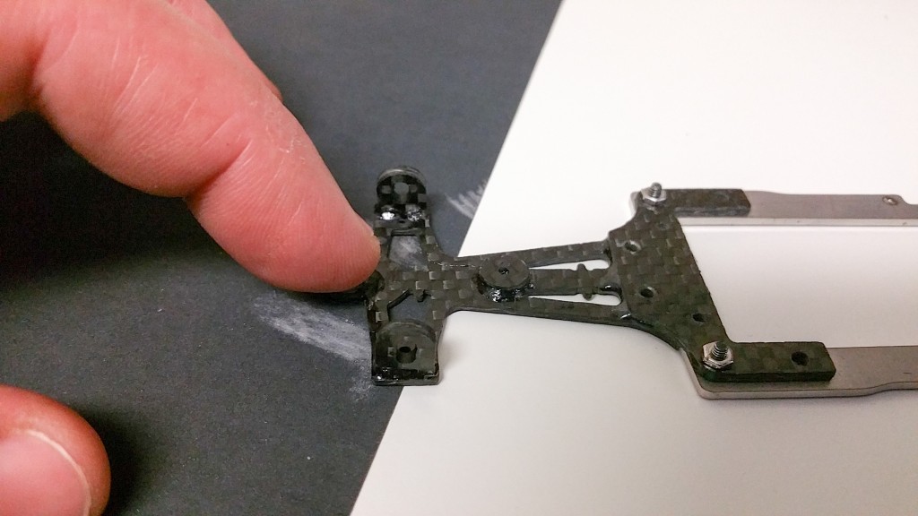
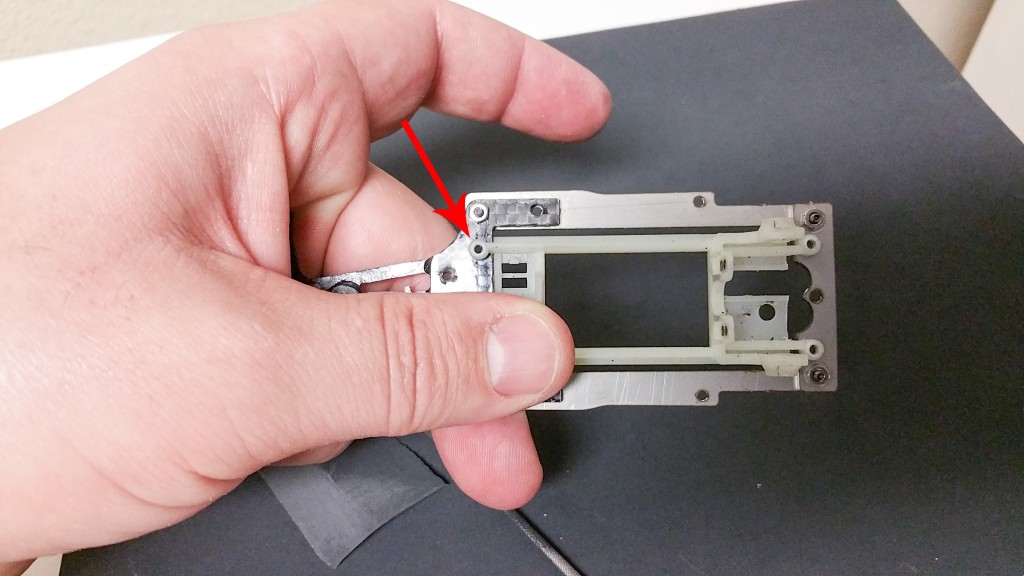
The guide holder is basically a plastic bushing that is glued to the carbon fiber frontal chassis, and there is not a lot of material protruding from the chassis. With a 500 grit sandpaper I removed the bump.
I got the chassis surface cleaned with a rotary wire brush.
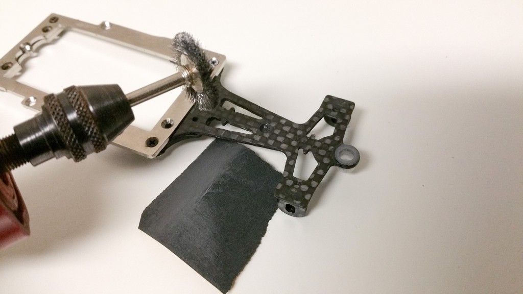
After that I cleaned up the screw holes.
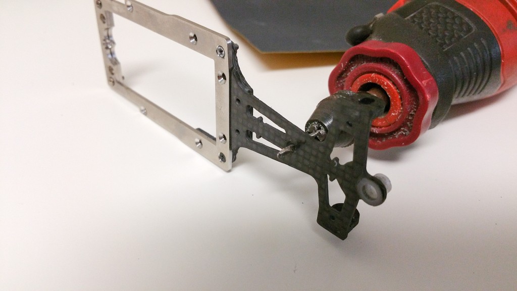
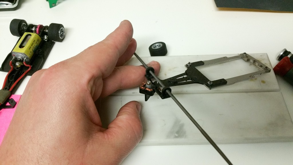
Proceeding with the transfer, I got the guide installed and continued to transfer the front axle. The front axle holder slot needed some filing, the axle wouldn’t go all the way up.
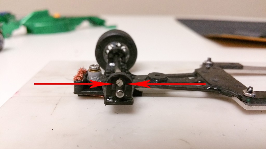
Very light filing was needed and the axle was free; with that I installed the front tires and noticed that they were too tall, there was a gap between my setup block and the guide.
Already at the highest axle adjustment, the only option is to reduce the diameter of the front tires.
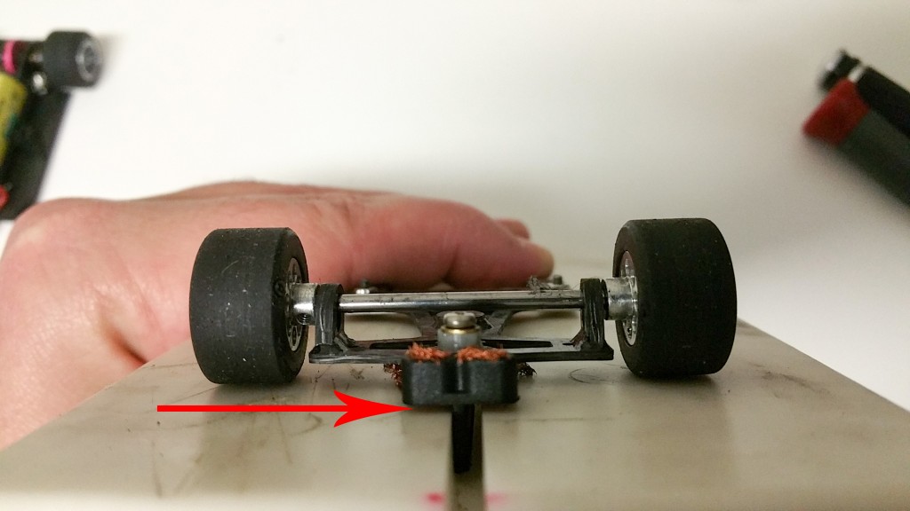
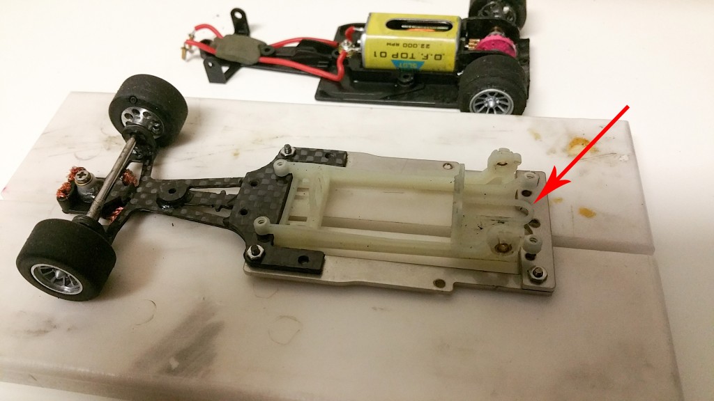
I leave the front tire issue for now and move to the motor mount. The motor-pod normally used with this chassis is from Scaleauto and it costs ~$50 – which I will pass. I grab a spare long can Slot.it motor-pod ($10) and verify that it would fit with a fell modifications.
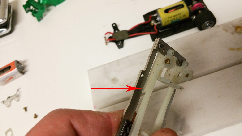
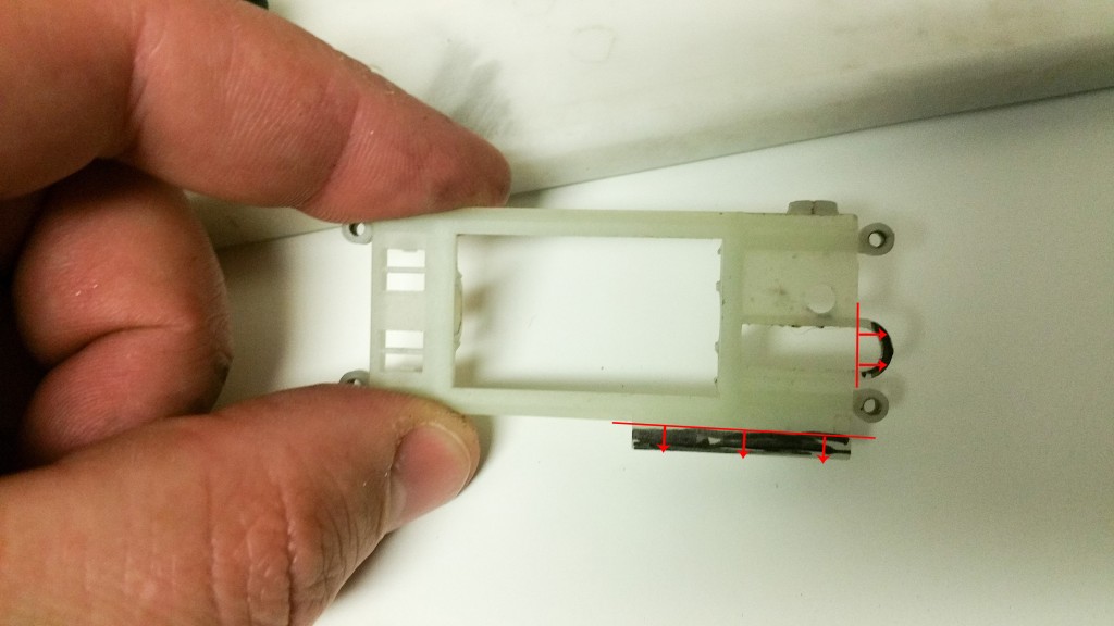
For the pod to fit all I need to do is remove the crown gear protection arch and the rear side support.
Here are the before and after shots. Rotary cutting disk and sandpaper were used to remove the material.
Now the pod fits. As I installed the pod screws I noticed that the front screw holes needed to be enlarged a bit so that the pod would float. With the motor-pod out of the way I used a 2mm drill bit to widen the holes.
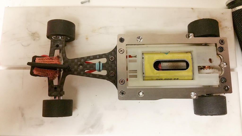
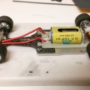
Motor-pod is in, next is the motor. As the gear is now on the opposite side of what I was originally using, I flip the motor upside-down so I don’t need to cross my wires.
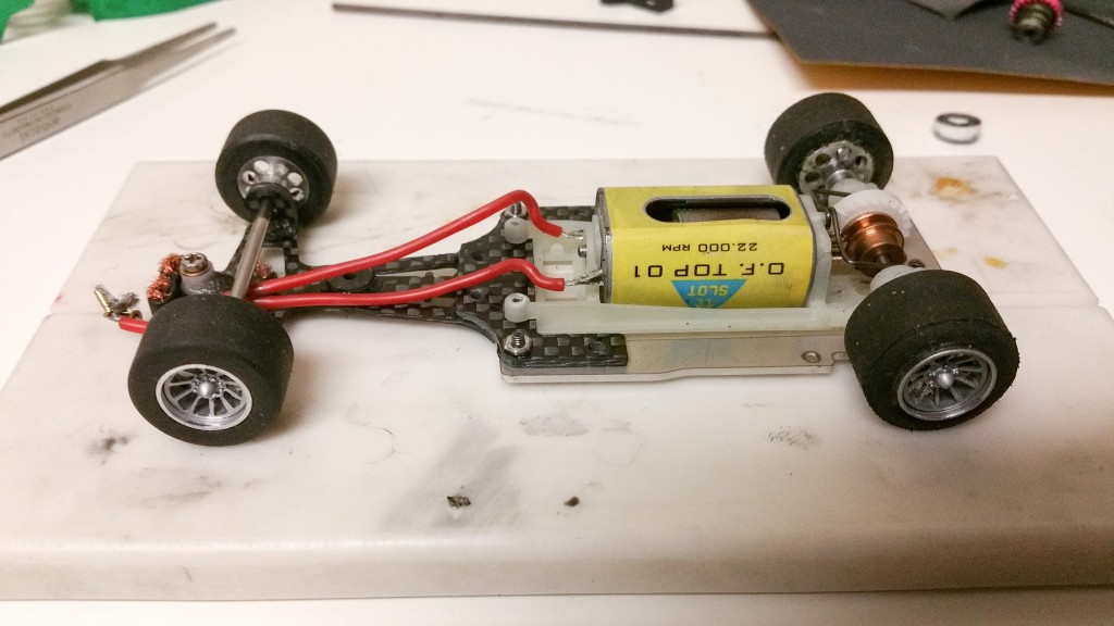
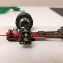
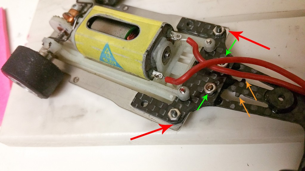
In this image:
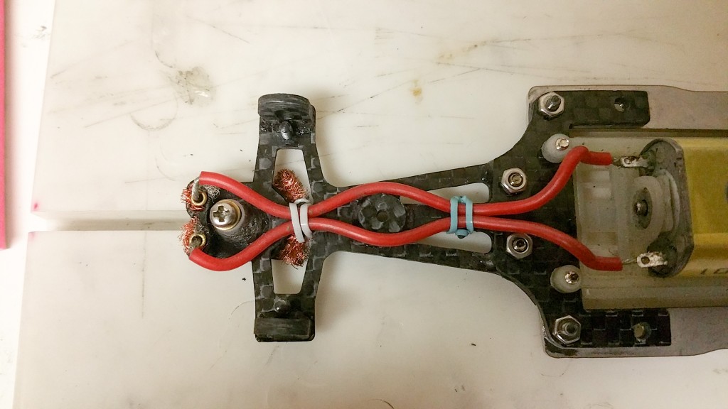
Green arrows: The carbon fiber frontal chassis piece is composed of a top and bottom plate which are glued together. There were two existing holes between the two plates where I installed screws for reinforcement.
Red arrows: I checked the body to chassis fit and saw that the corners on the carbon fiber plate ,just outside of the nuts being pointed, were rubbing against the body, I rounded them up with the rotary toll.
Orange arrows: Those two protrusions are used to hold the leads with the aid of a rubber band.
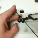
Found some small bands …
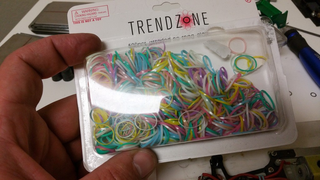
The bands were actually big for the application but lopping it around once got the job done. I will include a few with each of the chassis.
 I didn’t take any pictures of the front tire diameter reduction but I had to remove 1mm to get the wheels off the setup block – the front wheel diameter is now 18.5mm. Also, the official, 62mm maximum rear track for group A in 2015 will now be 64mm – simply because this chassis will not allow anything under 63mm.
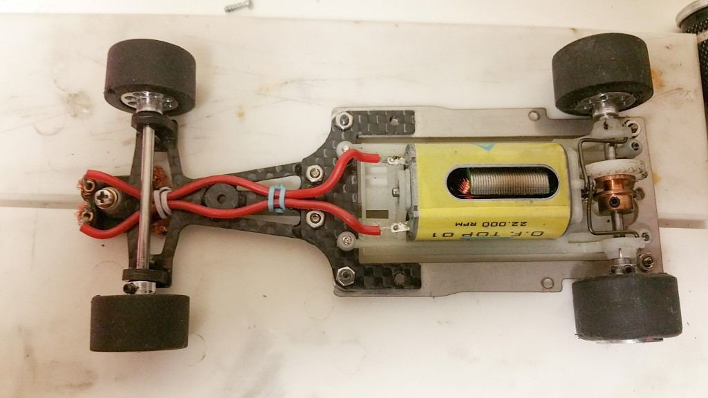
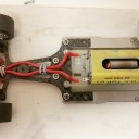
Here is the bottom shot. Measurements are:
Rear tire dia.: 20.3 (unchanged); Rear track: 63.5mm; Front tire dia.: 18.5mm; Front track: 62.1mm.
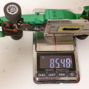
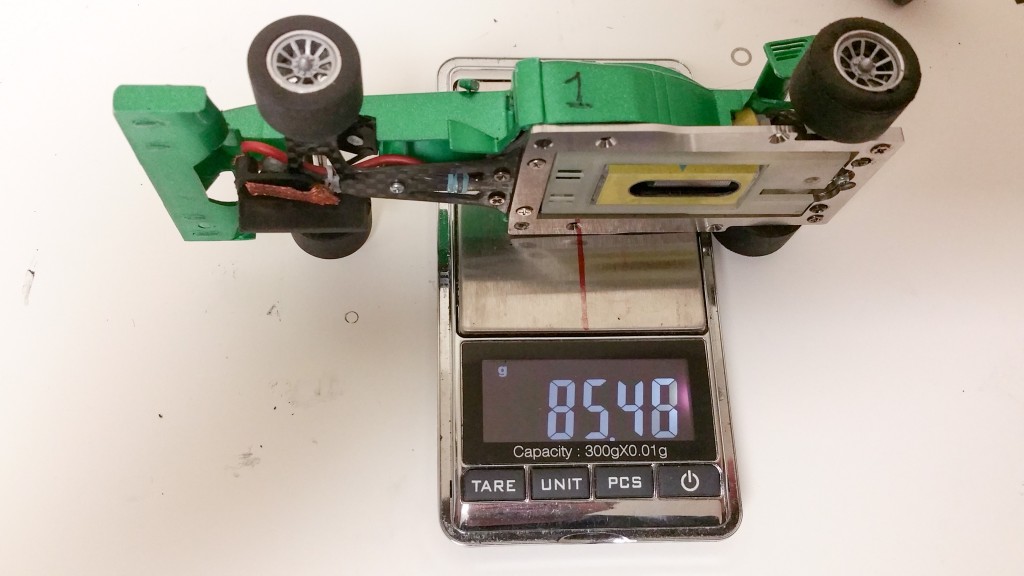
The car, without ballasts, gained some weight: 85.48gr.
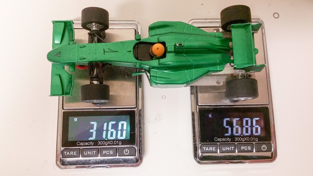
The weight distribution seems to be a bit off, with 64% in the rear and 36% in the front, but the car needs to hit the track before I can come up with any conclusions.
With the weight increase we may need more “power” to help accelerating and stopping the car, since I don’t want to add more costs to the series with the purchase of a new motor, we may race the series at a higher voltage.
Ary.
December 30, 2015 at 7:43 AM #8753Great write up, Ary! Thanks for the walk through.
January 2, 2016 at 3:22 PM #8770January 4, 2016 at 11:04 PM #8820Ary, thanks for the great review. I can’t wait to try out one of the new chassis. I can’t imagine not adding some weight to the front of the car to help balance it out.
Marty
January 5, 2016 at 2:06 PM #8823Marty,
That’s what I was expecting before running the car last Saturday but I was turning 3.7’s without even re-gluing the back tires (one of tires came unglued at the penultimate race and I didn’t fix it).
Ary.
February 11, 2016 at 8:57 AM #8893All,
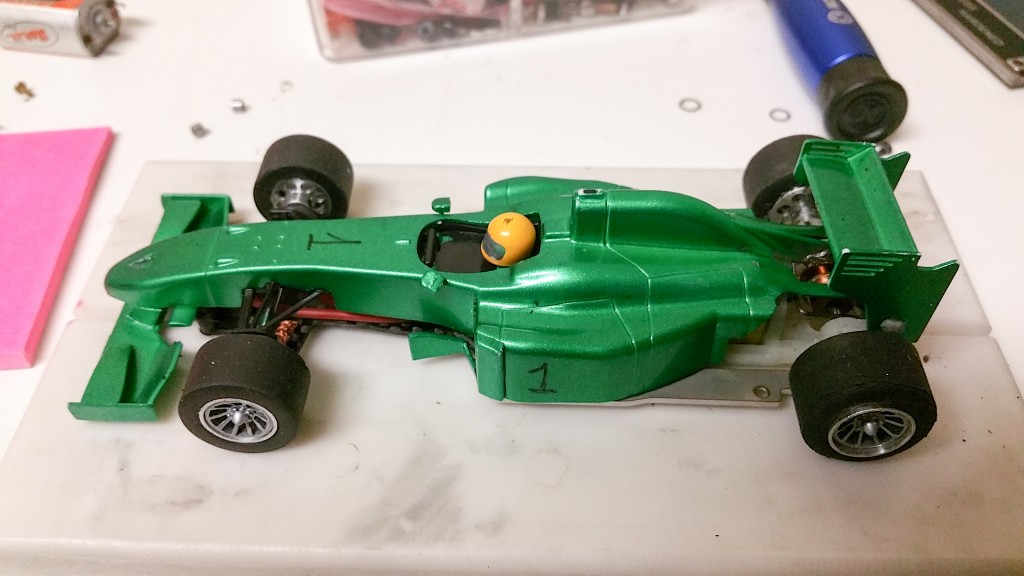
One more note for this build: a spacer needs to be added between chassis and rear body post. Reason: using the Slot.it pod, the rear axle shifted backwards slightly and the crown gear hits the body.
Also,
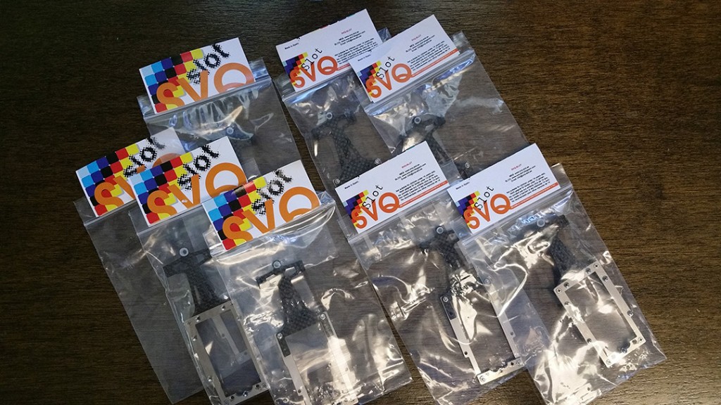
New chassis shipment has arrived:
I will be at the club tonight (Thursday 2-11-16) and during the club meeting (Saturday 2-13-16), you can get yours then – cost is $25.
March 29, 2016 at 8:33 PM #9010Last minute rule change:
Group B racers: we have changed the maximum track to 66mm (originally 68mm). This was done to help minimize the numbers of crashes due to wheel contact.
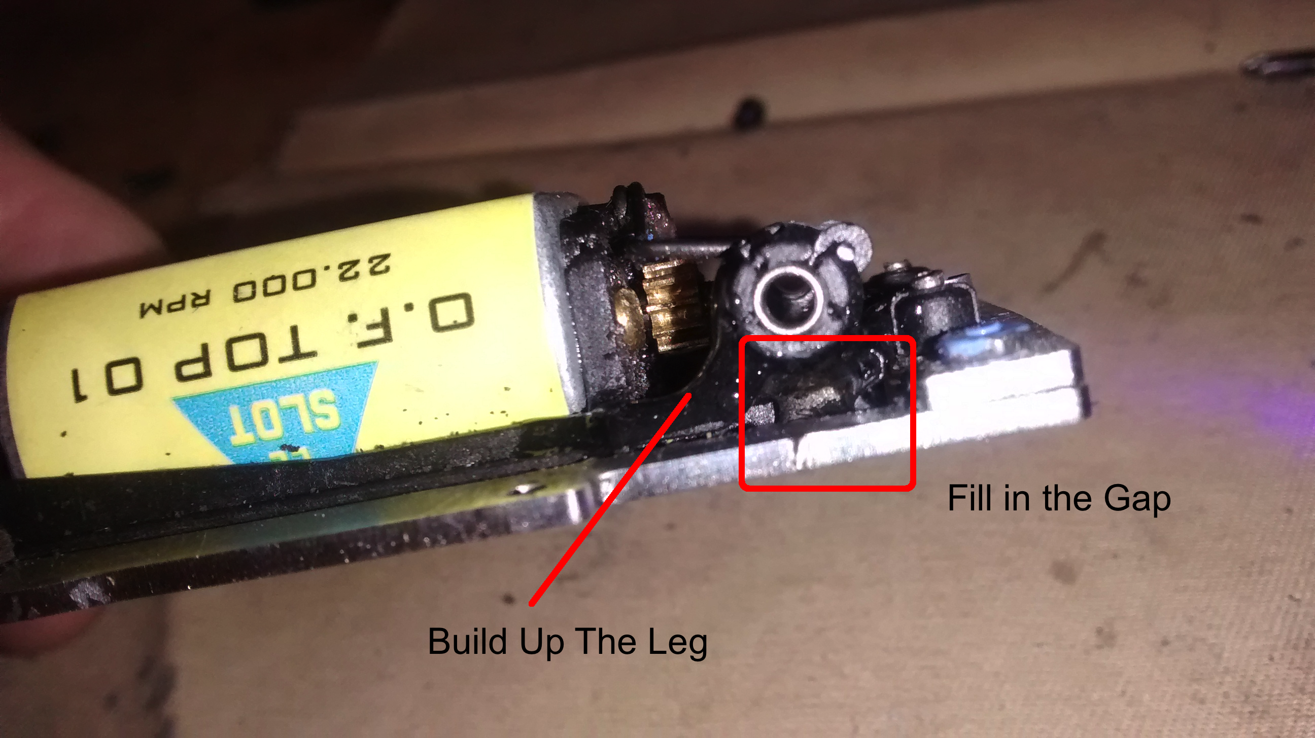
April 27, 2016 at 4:01 AM #9079The Slot.It long-can inline motor pod we are using has a gap below the bushing carrier and a medium size leading strut and tiny trailing strut. The mass of the steel chassis can easily break the struts in a hard crash (and can bend your axle). This happened to Marty, Dave and I. To prevent the struts from cracking, remove the rear axle and fill the little triangle gap under the bushing with Epoxy or Bond-IC. DO NOT use CA/superglue. ShoeGoo may work …. Realize that this is a preventative patch and has not been tested yet.
If you use Bond-IC you must cure it with its UV light. Epoxy needs to cure overnight. Wait until the material has cured before re-assembly otherwise you may either get some in the bushing carrier or weaken it with axle lube. Good Luck!
"... get on your bad motor scooter and ride!"
Sammy with MontroseApril 27, 2016 at 12:20 PM #9082Ary et al. – can we consider allowing the ScaleAuto 1/32 plastic pod (SC-6523) as an alternative to the Slot.It pod? This pod seems to have a more solid area around (below) the bushings and maybe it will be less likely to crack. It costs $12 in the US.
https://www.professormotor.com/product-p/sc-6523.htm
"... get on your bad motor scooter and ride!"
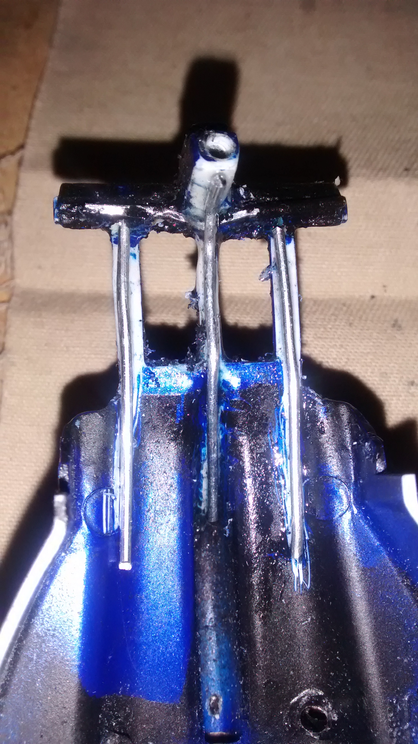
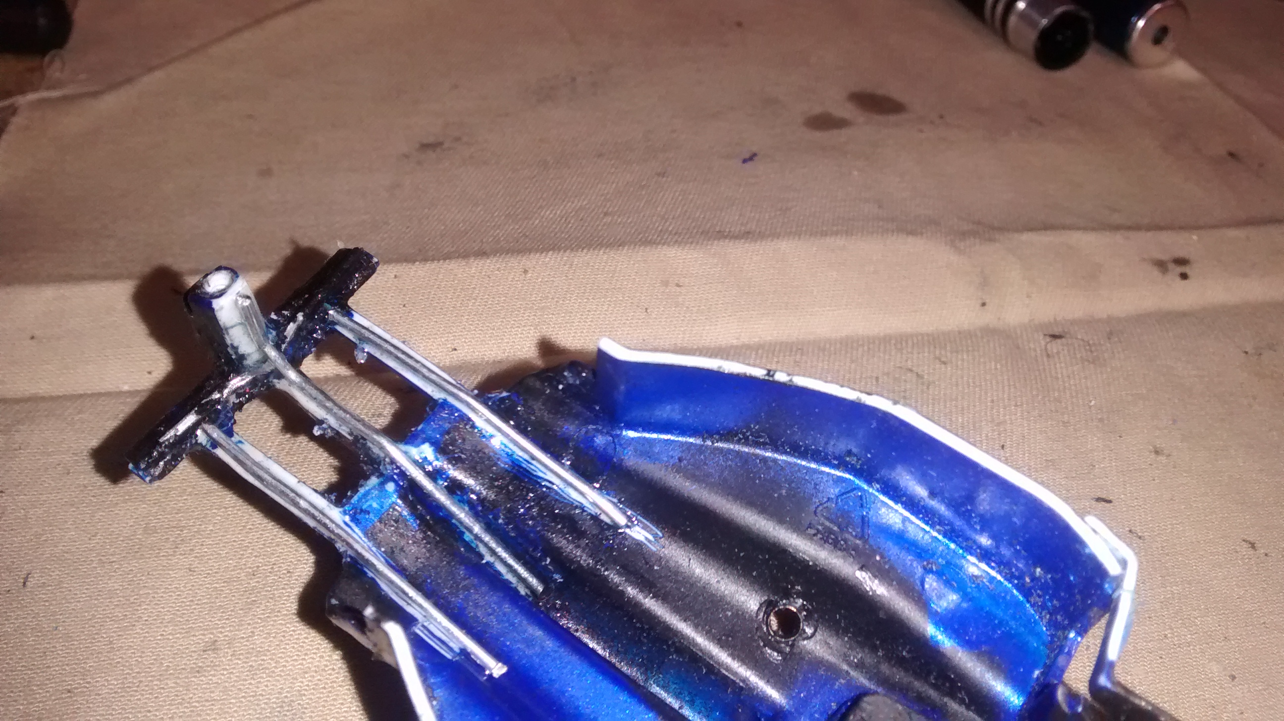
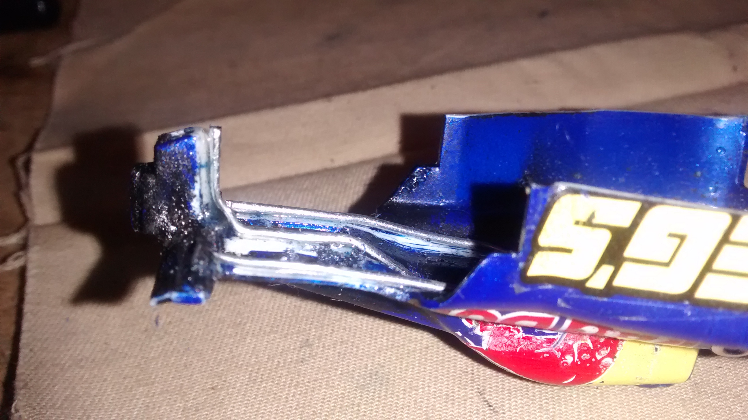
Sammy with MontroseApril 28, 2016 at 8:11 AM #9088The AllSlot Formula GP rear body post is only connected to the engine cowl with three thin stips of plastic. In a hard crash if these crack the body can jam on the crown and lead to extreme problems. Damage can possibly be prevented bonding piano wire (5/64 or thinner) to join the back of the post to the body and to reinforce the other bridges to the wing-T. A wire on the bottom of the wing-T can be used to prevent flexing of the wing-mount.
"... get on your bad motor scooter and ride!"
Sammy with MontroseMay 9, 2016 at 4:59 PM #9119NEXT TIME WE RACE THESE
Based on our experience I request we consider these changes in specs:
- We use the aluminum ScaleAuto motor pod (to prevent carrier strut breakage).
- We allow Slot It (PA20-AL) or Slotting-Plus (SP02195) F1 hubs.
My experience with the AllSlot hubs is that the threads in the hub for the grub screw seem to strip easy (I have three pairs of AllSlot wheels where One of the pair has stripped threads). The PA20s have a solid hub so no more need for o-rings and the weirdness matching tire diameters during truing when the tire pushes down into the airhub channel (even when o-rings are present) and marbles itselft to death.
PA20s have a 12mm dia rim, 14.5mm diam nub, 11.5mm wide with a 6mm wide nub/nib. The AllSlots measure the same with a 7mm nib. The NSR 5020? tires have a 7mm nib-slot but seem to fit tight and centered on the PA20s. Maybe some glue or one o-ring could be used if they were to slip.
The SP021950s (aka. SLPL40114512 ) use a 2.5grub. They are spec’ed at 14.5dia-nub at 12mm wide rim. I used these on a custom project and they are durable and good looking wheels.
"... get on your bad motor scooter and ride!"
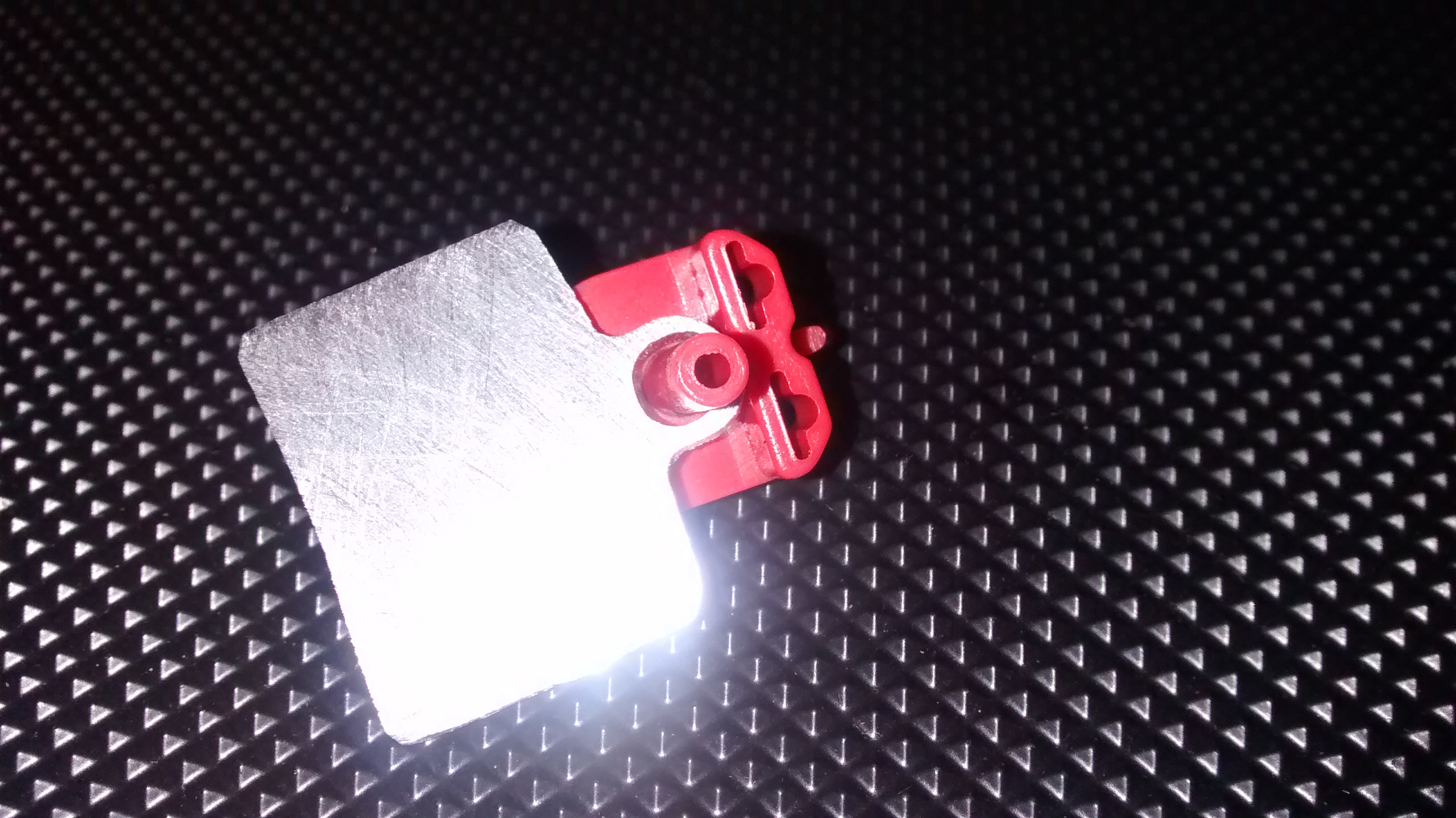
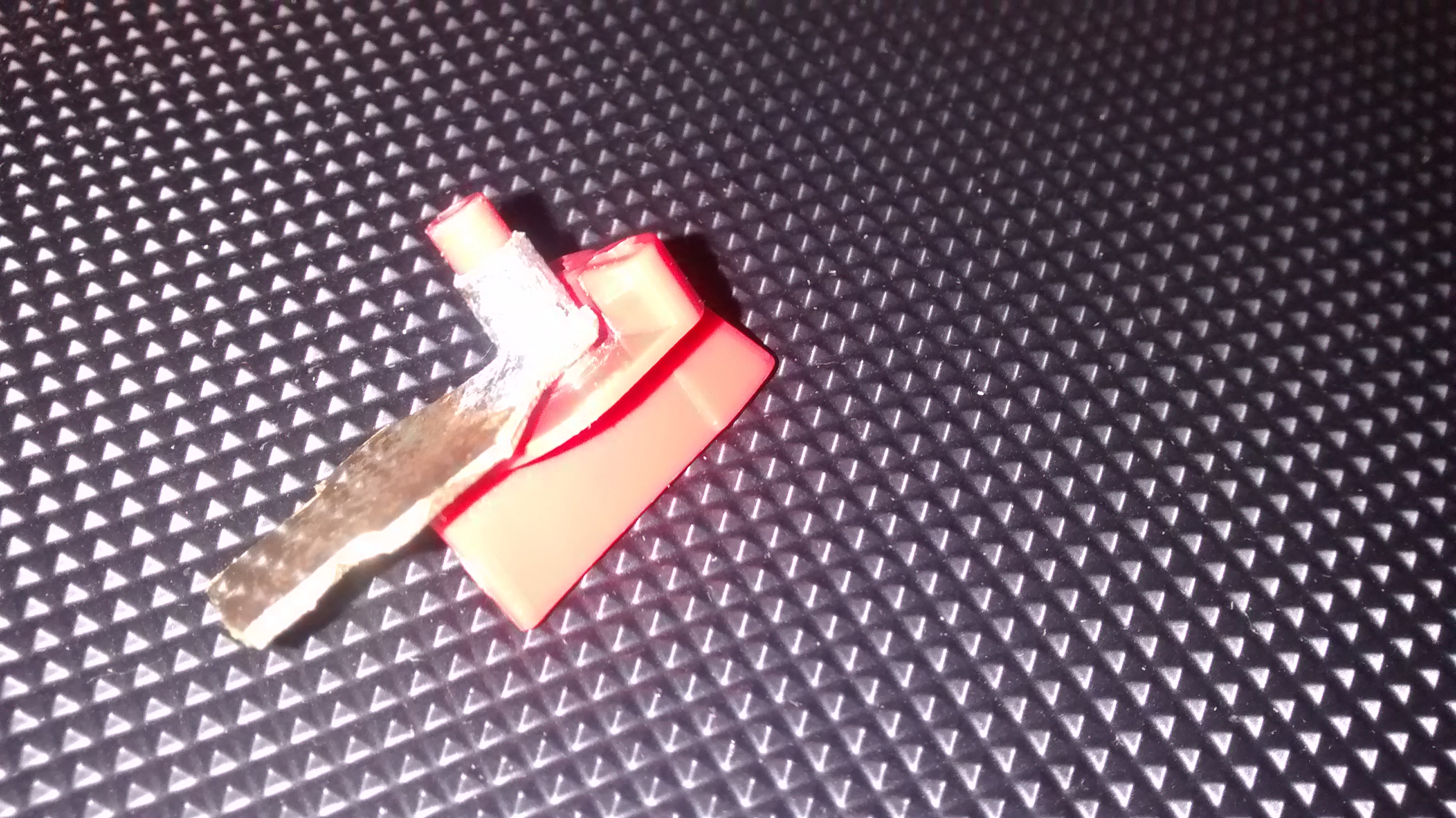
Sammy with MontroseJune 1, 2016 at 1:40 AM #9168The SVQ chassis has a flimsy nylon sleeve glued inside a thin ring of carbon-fibre. The guide rocks because the sleeve is not thick enough to give a tight fit with the typical shaft of a Slot.It or ScaleAuto guide. With the added mass of the stainless chassis and the power of the long-can motors it’s not hard to break this flimsy Guide-Boss. Preventative or restorative reinforcement can be done with a metal patch. (1) Alejandro has CNC’ed some aluminum plates appx 2mm thick that can be bonded to the top of the carbon-fibre. Dremel to fit – keep some ‘wings’ to reinforce the strut area.
(2) I have used some 1/24 brass tongues (1.5mm thick) with brass tubing soldered together into a patch I bond with epoxy to the bottom of the chassis (it can also be bonded on top). The tubing is 5mm (6/32) outside diameter (4mm – 5/32 ID) – by 4mm tall. BTW the guide becomes incredibly smooth in its sweep and has no forward-back rocking.
Again, Dremel to fit and keep some ‘wings’ to support the struts/suspension arms. When mounting below the chassis, paint the bare brass with nail polish or enamel to prevent shorts, (do not paint below the guide b/c it will bind).
"... get on your bad motor scooter and ride!"
Sammy with Montrose -
AuthorPosts
- You must be logged in to reply to this topic.

