Home › Forums › Slot Car Talk › Tech Tips / Q & A / Tutorials › Fly Ferrari GTO Slot.It Converson Project
- This topic has 3 replies, 3 voices, and was last updated 14 years, 4 months ago by
 Autorama.
-
AuthorPosts
-
June 6, 2011 at 9:09 PM #294
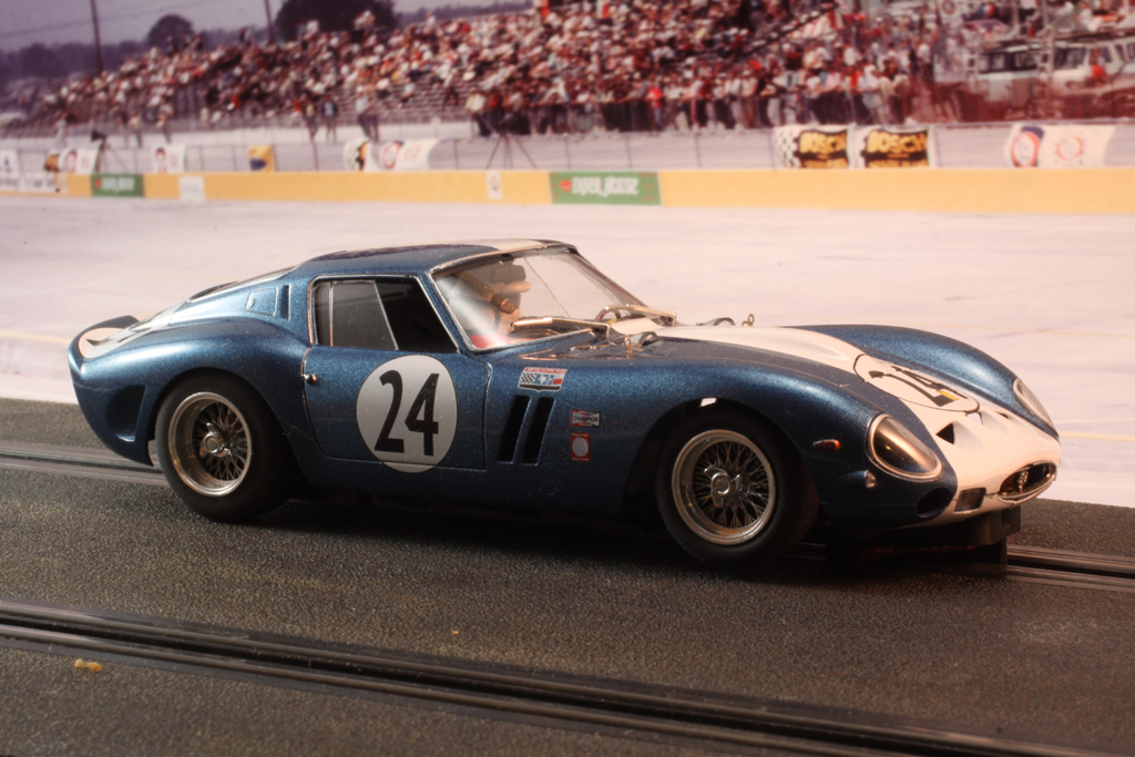
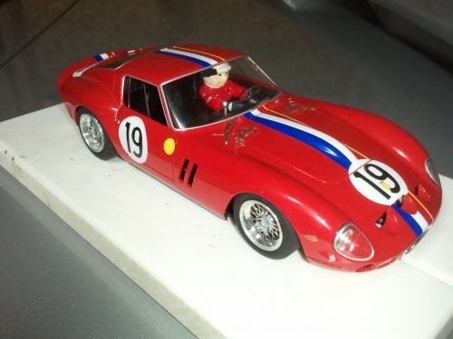
 Soon after the release of the Slot.It Ford GT I started looking to see what other cars the chassis might fit. The Fly Ferrari GTO, of which there are many variations, is a near-perfect fit. These cars have beautiful bodies but with the front-mounted motors, the cars don’t run well without magnets. Replacing the Fly chassis with the Slot.It sidewinder chassis promised to work much better. The BRM wire wheels really add the finishing touch.
 After purchasing a couple of the Slot.It SICS18t-60 GT40 chassis and disassembling the Fly GTO, I fit the two together to see what kind of mounting would work best. I decided to install a couple of mounting blocks that would bolt to the body and then the Slot-It chassis would bolt to them. I had some Plastruct rectangular tubing in my drawer, measuring ¼” X 5/16″,that looked like it would work. You could use other plastic or wood the same size instead. I cut a piece of the tubing to bolt to the front mounting posts.


In order to re-use the original mounting screws, I cut out the top of the tubing above the mounting posts. If you use longer screws you could go through the entire tubing. Later, I determined that I needed to lower the front of the body slightly so I cut 1 mm off of the body posts. Besides that, cutting out the bottom of the nose to clear the guide is the only other modification to the Fly body. The only modification to the Slot.It chassis was cutting off the ears that project forward on either side of the pickup.
In the rear, I made a template out of card stock to fit over the rear body mount. This piece fits in where the sides and rear of the body meet the roof. After testing the fit of the template, I cut the plate out of .030 sheet styrene. If you click on the image below, the full size image will open and you can “Save Picture As” to your computer. If you then print it actual size you can use it as a starting template.

I super-glued a piece of plastic stock to the rear of the body, above where this plate mounts, to help hold it in place. A screw into the rear mounting post secures the plate.

I cut another piece of the Plastruct tubing and screwed and superglued it to the chassis side of the plate.


Next, I filled the two pieces of tubing with PC7 epoxy. This is my favorite structural epoxy; it is very sticky, bonds to just about everything, and cuts and drills easily. It is also very thick and holds it shape while it cures. It is slow curing, which means you have a lot of time to work it, but it needs to dry overnight.
Putting the chassis in place I marked where to drill the chassis holes. I installed the Slot.It SICH64 1 mm offset motor pod in the GT40 chassis and fastened the chassis to the adapters. Now that I had the chassis in place, I could see how much room I would have for the interior. Of course, the easiest thing to do would be to put in a flat piece of plastic and mount a driver’s head and arms on top, but I wanted to retain as much of the interior as possible. After removing the driver, belt harness, and steering wheel, I used a razor saw to make trial and error cuts on the interior to clear the motor and chassis.

I ended up making the cuts as shown in the photo. The bottom horizontal cut would eliminate the transmission tunnel so I made the cut through the center a little lower, leaving the top half of the tunnel in place.

I cut a piece of .010 sheet styrene and made a right angle bend in it and glued it in place against the vertical cut and the horizontal part extending backward to the package tray. I then cut another piece to use as the new floor, gluing it to the bottom of what was left of the transmission tunnel and folding it up to wrap up the outside of the interior tub sides.


Next, I masked off the dashboard and tranny tunnel and sprayed the rest of the tub flat black.

I cut the driver figure into 9 pieces as shown. There will not be much of the torso left, only a sliver of his chest. His butt and the bottom of his legs were also cut away.


I glued in the steering wheel and then the driver pieces shown above. There were some slight gaps from the arms to the shoulders that I filled in with PC7. I then detail painted the driver figure.


In retrospect, I should have painted the gloves and legs before I glued them in place. The weight of the original interior tub was 9.3g; the weight of the modified tub is 5.9g.
Here is the body with the finished adapters and interior tub installed.

For the wheels, the natural choices are the gorgeous wire wheels from BRM. The S-111 22X9 mm rear wheels and tires for 3/32″ axles are the right size. I could not find the fronts for 3/32″ axles so I used the S-112 20X7 mm wheels and tires for Ninco axles and enlarged the axle carriers on the chassis. This axle assembly then fit fine.
It turns out that the rear BRM wheels and tires will not fit within the GTO body; I needed hubless wheels. I had a pair of Super Wheels SS (15X8) hubless wheels that would fit but I wanted to use the BRM wire wheel inserts. It took some work to remove the pieces from the BRM wheel. There is an outer rim insert that is very tight, holding in two photoetched wire wheel inserts separated by a small hub. The only way I could remove these pieces was to cut the wheel from the backside with a Dremel cutoff disc. I ended up cutting into the inserts slightly on my first try but it doesn’t show too much in the finished wheel.

A little more difficult to deal with is the fact that the photoetch inserts and rim will not quite fit in the Super Wheels. This presented an opportunity to use my new lathe. I do not have any machining tools but after chucking an axle and Super Wheel in the lathe, I used a number 11 blade to scrape the inside of the wheel enough to get the BRM parts to fit. A Dremel tool or drill could be used instead or you could use other inserts. I also used a Dremel to remove part of the projecting hub on the wheel to get enough depth for the BRM parts to fit.

One last note on the BRM wheels; I had several sets of the wheels and when I went to glue on the knockoffs, I noticed that some pairs of wheels had the proper left and right hand knockoffs while others had two the same.
The last step is to cut off the back end of the Fly chassis that holds the exhausts
 .
.This part contains the original chassis mounting post. I made two cuts to this post to make up for the thickness of the rear adapter plate and reglued the post together. Now the exhaust panel can be installed or left off for racing.

Finally, here is a look at the completed chassis.

I wanted tires with an appropriate size and profile. I currently have a set of 1405 Yellow Dogs .840″ O.D., .350″ Wide.
Next up is tuning the car for optimum speed.
Off to the track!
Russell Mill
June 6, 2011 at 10:30 PM #1389Russell,
Thanks for taking the time to this tutorial. I will start working on mine as soon as I can; it is good to know all the parts I will need, specially the hubless wheels.
June 7, 2011 at 8:53 PM #1392Russell,
Thanks for sharing your story on your beautiful Fly/Slot It Ferrari GTO. It is a stunning car that now runs as good as it looks. I enjoyed reading how the transformation took place.
Marty
October 12, 2011 at 10:15 AM #1503Russell,
It took me 3 months but I got it done. Thanks for the tutorial.

-
AuthorPosts
- You must be logged in to reply to this topic.

1 comment for “Fly Ferrari GTO Slot.It Converson Project”