
Home › Forums › Slot Car Talk › Tech Tips / Q & A / Tutorials › El Piloto Series Build Log – Blue printing Slot.it McLaren F1 GTR
- This topic has 6 replies, 3 voices, and was last updated 15 years, 3 months ago by
 Autorama.
-
AuthorPosts
-
March 14, 2011 at 4:53 AM #209
Short Series Description:
The El Piloto is an iroc type slot car racing series. The idea is that each available track lane has its own slot car. The slot cars stay on a specific lane and the drivers rotate trough all lanes.
At the end of the series, the winner will choose one of the slot cars as a prize. The remaining two models will be auctioned within the club.
Build Budget & Costs
Our club track has three lanes. The budget for the series was U$240 (six racers fronting U$ 40). After some research, I chose the Slot.it McLaren F1 GTR white kit (Part# CA10Z – U$ 49.99), Sidewinder Conversion Kit (Part #KK13 – U$17.99), P6 Compound 20X11 Tires (Part# PT25 – U$ 8.99) and Wood Track Pick-up Guide (Part # CH07 – U$ 5.99). This setup had already been tested and performed very well.
The total amount spent per car on parts was U$ 82.96, bring the total to U$ 248.88. Some of the other materials used I already had and are not included on the build cost (paint, glue, cooper braid, etc). I could have chosen different liveries instead of a white kit but I wanted to personalize the slot cars, you can add another U$ 30~50, to cover paint, decals and glue.
Build Log:
Although I had a build sequence already planned some things changed along the way. I will be showing everything that had to be done, including the mistakes. If you are using this log as a basis to build your model, read its entire content before starting to avoid the mistakes I made.
_____________________________________________All main parts arrive: 3x McLaren White Kit, 3X Sidewinder Kit, 3X P6 Tires

The first thing planned was to “bake” all the chassis. For that I disassembled all the models. You can see all the parts below.

“Baking a chassis” is a process used to straighten the plastic chassis that is usually slightly warped on a stock slot car. Slot.it has a great description of this process (https://slot.it/Download/FAQ_PDF_en/1-ArtOfChassis.en.pdf).
The most important part of this process is the use of a perfectly flat iron plate that can accommodate you chassis. The plate I use is machined and was found at a scrap yard (U$20). You will also need an assortment of magnets, a boiling pan, a baking pan and an oven.

If you don’t feel like digging through a scrap yard, Technology-SlotCars.eu has released a tool specially made for straightening chassis (https://www.technology-slotcars.eu/index.php?ind=articoli&op=entry_view&iden=52).
Below you can see the magnet placement. The idea is to have all the chassis corners and large areas covered.

Fortunately, I can bake all three chassis at once.

Place your iron plate inside your baking pan.

Meanwhile, boil enough water to cover your chassis with an additional inch of water on top. At the same time, start your oven at 250F.
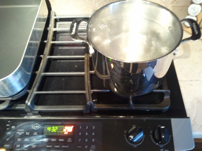
When the water boils, place your baking pan on your oven tray, pour the water (it is a lot easier to add the water where you baking pan is going to rest instead of moving the pan with boiling water), close your oven and turn it off.
You will need to wait for the whole thing to cool down, this can take 8 hours or more, you can leave it cooling overnight.

As the chassis were cooling I went to tackle the plain white bodies. The first thing done was to remove the side panels that came glued to the main body (not pictured). This was done with a Dremel and a round gridding tip. This was also done because of the paint scheme I had chosen as you will see later on.

At this point the parts are resting on a box ready to be primed. I used Tamiya white primer as one of the colors is Yellow and grey primer would be hard to cover.
Spray lightly and do it two or three times covering all the sides.

While my primer is drying I spend some time checking the RPM on each motor before break-in. I marked the motors from one to three in order to check it again later. Our club normally race at 10 Volts and that is the voltage I used on this process.

I left each motor running for 3 minutes and checked the RPM.
Here are the results:
• Motor #1: 17.5K RPM
• Motor #2: 17.8K RPM
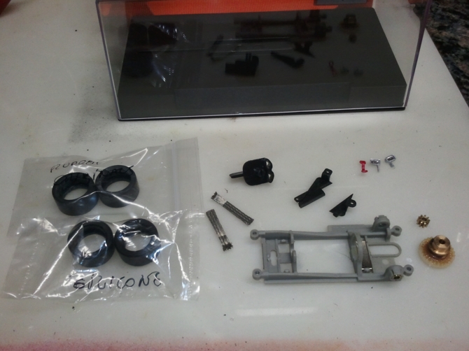
• Motor #3: 17.6K RPMNext on the list was the exchange of parts between the stock inline motor pod to the sidewinder pod. For this you will need a 0.035″ hex driver. We will need to transfer the axle and wheels to the new pod.

Here is how it should look after it is done:

As soon as the chassis have cooled down from the straightening process, I move to assemble the pieces together.

At this point I start removing some plastic flashing from the sides of the motor pod, just enough for the pod to have freedom of movement when resting on the chassis. I chose to scrape the material off with an X-Acto knife.

Next I sand the pod “bed”, the area around the chassis were the pod will rest. Again, slightly.

When the sanding process is complete, I assemble the pieces together. Now there is some room for pod movement.

Front axles and wheels go in and you have a rolling chassis.

With the primer coat dry I move to paint the main part of the body. The cars will be mainly silver with an accent color that indicates each lane; in our case yellow, blue and green.
The same process used for priming is used here; light multiple coats.

The accent pieces follow.
The reason I removed the sides earlier is that it is a lot easier to paint a part one color than it is to mask it and paint over a previous one.


While the pieces are drying I go back to the chassis and start on tuning. The original silver braid is replaced by more malleable cooper braid, I also unpack the P6 compound tires to work on next.

Here is how the braid looks from the top.

I use a wire brush to “fan out” the braid after installed. It helps flatten and widen the braid. You can see the difference on the picture bellow, the lower braid was not worked on.

Now we tackle the new tires. For this you will need a tire truer. You can also try doing this with a Dremel but the results are not optimal.

Since there are several types of tire truers, I will not be describing this process. Basically you want all tires to be true, and to have the same diameter.
We have ten races and a few practice runs on this series, with only one spare set of tires on the budget, I removed as little material as possible from each tire set.
You will also want to round the edges of your tire. I use a coarse emery board to achieve this.

This is how the chassis sits after truing the rear tires. The front of the chassis was hitting the setup block, which indicates that it would hit the track.

THE GUIDE MODIFICATION LISTED BELOW DID NOT MAKE TO THE END PRODUCT, IT WAS REPLACED BY A WOOD GUIDE. THIS “MISTAKE” ADDED AN HOUR OF WORK.
The stock guide is designed to be used on plastic tracks were the contact rails are slightly raised; our club track is braided were the contacts sit flush with the track. You can see this when you remove the braid from the stock guide, you will notice that the guide sits above the chassis, I needed the guide to sit flush with the chassis.
To fix this problem I added a washer between the pick-up guide and the chassis. After adding the washer, the guide did not move freely. The space for the guide shaft on the chassis was still the same but the guide shaft length had been reduced due to the washer . To fix this problem I had to deepen the recessed area were the guide shaft locks into the chassis, that was done with an X-Acto knife.

This picture shows (although hard to see) how the front of the chassis was raised after the guide modification.

Front tires truing and sizing is next. I would normally buy Zero Grip tires for this application, but our budget would not allow this purchase.

My personal preference is to have the front tires not touching the track on a straight. I also like to have little vertical play on the front axle (I don’t want the axle to wobble). After inserting the front axle raisers (AKA chassis spacers – not pictured), I setup my front tires raised, approximately 1mm, from the track. This is done by removing material from the tire and constantly checking the clearance with a setup block.
Here is how it looks:

Here you can see how much material had to be removed.

A thin coat of nail polish is then applied to the front tires in order to reduce traction. I use a mixture of 70% nail polish to 30% acetone.

At this point you finally have a rolling chassis.
With the chassis part done I go check on my painted parts. I had almost forgot to strengthen the rear spoiler, this is something I should have done before painting them, fortunately I only painted the top and the strengthening will be done on the back.
You will need Epoxy (5 minutes), scissors and a roll of drywall fiberglass tape.

For this procedure you could use epoxy only, but the fiberglass tape will increase the rigidity ten-fold. Cut strips of tape wide enough to cover the spoiler posts without passing the spoiler edge. Apply it as show on the pictures.


Mix your epoxy glue and apply a thin coat on top of the fiberglass tape.

Trick: Use a small Post-It notes pad to mix your epoxy. The glue will not go thought sheets.

At this point I notice that I forgot to paint the small body pieces. Here they are:


With the all the body pieces painted, I start assembling it.

BIGGEST MISTAKE FOLLOWS
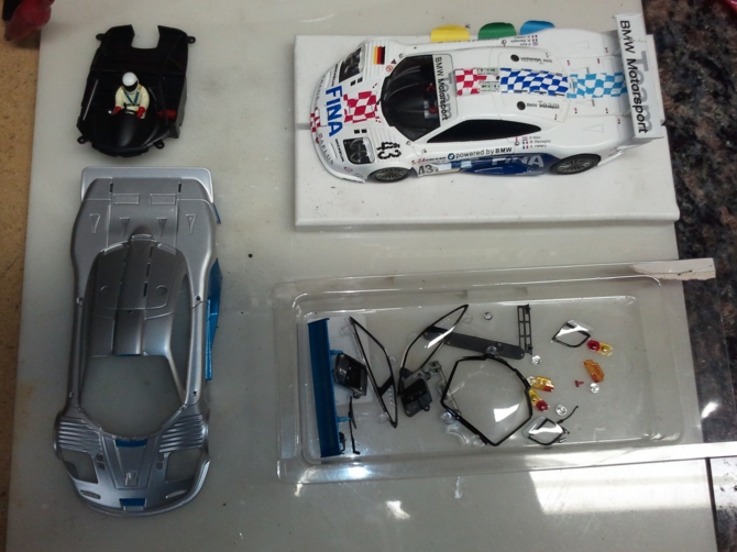
After glancing at the models semi-assembled; without thinking, I go further.
Using a ready-to-run McLaren Models as a guide, I gather all the small pieces from the white kit on a tray and get ready to the task ahead.
To “glue” the pieces, melt them really, I used a soldering iron set on low temperature.

In this picture you can see the center rib posts already glued while the window posts are not.

After melting all small parts of each car, here is the result:
THIS IS WHEN I REALIZE THAT I STILL NEED TO APPLY DECALS. AFTER DECALS COMES A CLEAR COAT AND YOU CANNOT APPLY A CLEAR COAT OVER CLEAR PLASTIC (WINDOWS). THIS MISTAKE ADDED ANOTHER 3~4 HOURS TO THIS BUILD.
Now I go back to spend some quality time with the motors. After removing the inline pinions (not pictured), I set all three motors on break-in blocks (piece of 2X4). All motors were broken-in at 4 Volts for approximately 30 minutes.


RPM readings followed:

Here are the results:
• Motor #1: 19.2K RPM
• Motor #2: 18.8K RPM
• Motor #3: 18.2K RPMThere only reason I read RPM before and after motor break-in is to show the advantage of the break-in process.
Next; installing the sidewinder pinion. You will need a pinion press.

The next step is something that I never had to do before. Because I removed little material from the rear tires, they were touching the armature axle and I had to trim it. After marking how much I had to remove, I used a cutting wheel on a Dremel.


Here is the end result:


After installing the motor, the wires had little slack when attached to the guide. That was fixed by re-soldering the wires, this time pointing to the guide.
The motor on the left had been fixed, the one on the right was stock, still pointing to an inline guide setup.

For my own records I read the RPM at the wheel of each car. For an inline setup on our club track, the average RPM at the wheel is approximately 7K. As I know found out, 6300 RPM on a sidewinder setup produces the same lap times. My guess here is that there is a greater loss in torque using an inline setup, I still need to verify this.
Here are the results:
• Car #1: 6350 RPM
• Car #2: 6200 RPM
• Car #3: 6150 RPMI had planned to spend some of the budget on pinions but after testing the cars and checking their lap times I decided not to; instead I purchased wood track pick-up guides. Those are a lot deeper than the stock guides and perform a lot better on our track.

Slot.it wood guides come with a “defect” from factory, there is always a piece of left over plastic from the mold.

Remove it with an X-Acto knife, I also like to round the edges when doing this. The picture bellow shows a fixed guide at the bottom.

I trim the back side of the guide as I had previous problems with that piece hanging on the chassis.

Here is an image to show the difference in depth and lenght between the wood and stock guides.

At this point the cars are ready to race, only waiting for decals.
Here are all the parts left over from the original white kit. The side mirrors and hook were not installed as they break easily.
All the parts removed from the original kit will be included with their respective slot car, that will later serve as prize or be auctioned.
The decal sheet should have a tutorial on its own, not today. The decals are acquired through websites that provide vectorized logos, some of those are: https://www.brandsoftheworld.com/ and https://www.vector-logos.com.
You need a vector based software (Adobe Illustrator or Corel Draw) to edit those files and size them according to the model you will be applying the decals on.
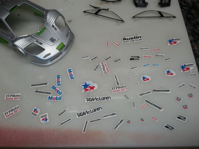
After imagining how the car should look like and looking at real life models I made a full decal sheet ready to be printed.
The printer should have a high definition in order to show detail. This is when camaraderie prevails. I do not own a good printer but one of our members was king enough to print and clear coat two sheets of decals — Russell, you rock.
Details on printing waterslide decals can be found here: https://www.ehow.com/how_4884251_make-waterslide-decals.html
The picture below shows the decals sheet ready to be used.

At this point I have to undo my mistake. All windows and clear plastic parts needed to come off. Dremel and round gridding tip, the sequel, X3.

After cutting all the decals I think I will use in the model I can start applying them.
The first model took a lot of time to do. Finding a good position for decals and trying to make the model look good is a long process. There are several decals I used that were no wider than 2mm; use tweezers and a steady hand. I was too busy trying not to make any mistakes (which I did) and I ended up not taking any pictures.
After I was satisfied with the decal placement, it was time for the clear coat.

From that point on I had to re-glue all the windows, etc. I could not use the soldering iron method as the posts had already been melted, epoxy was used instead (not pictured).
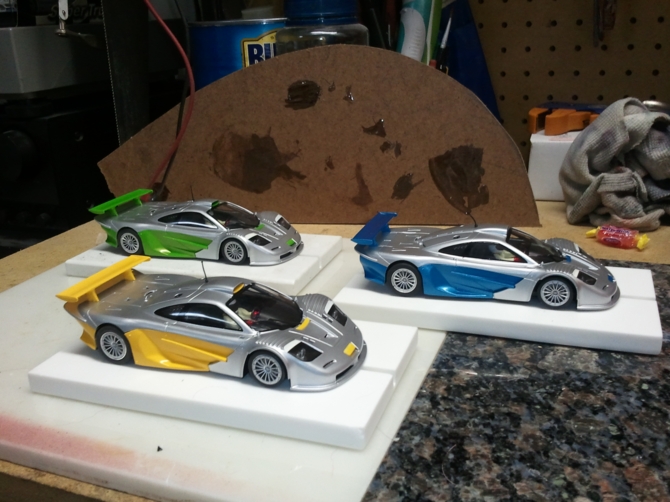
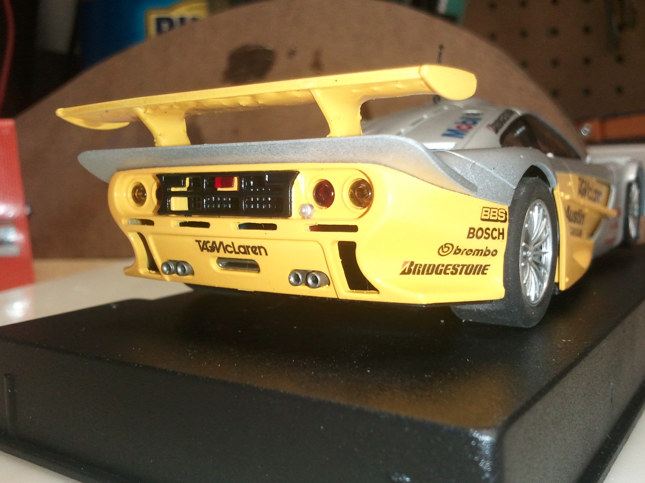
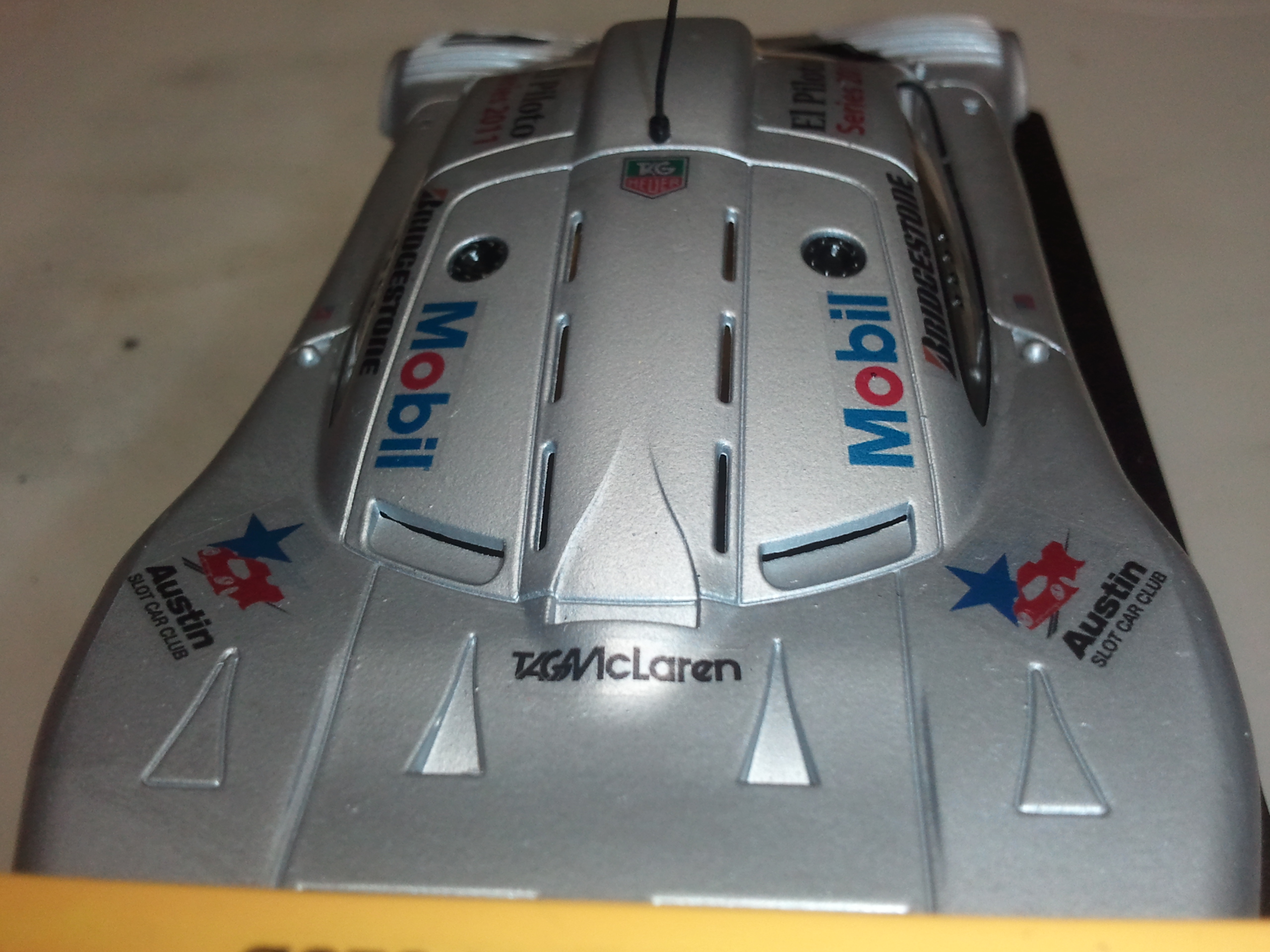
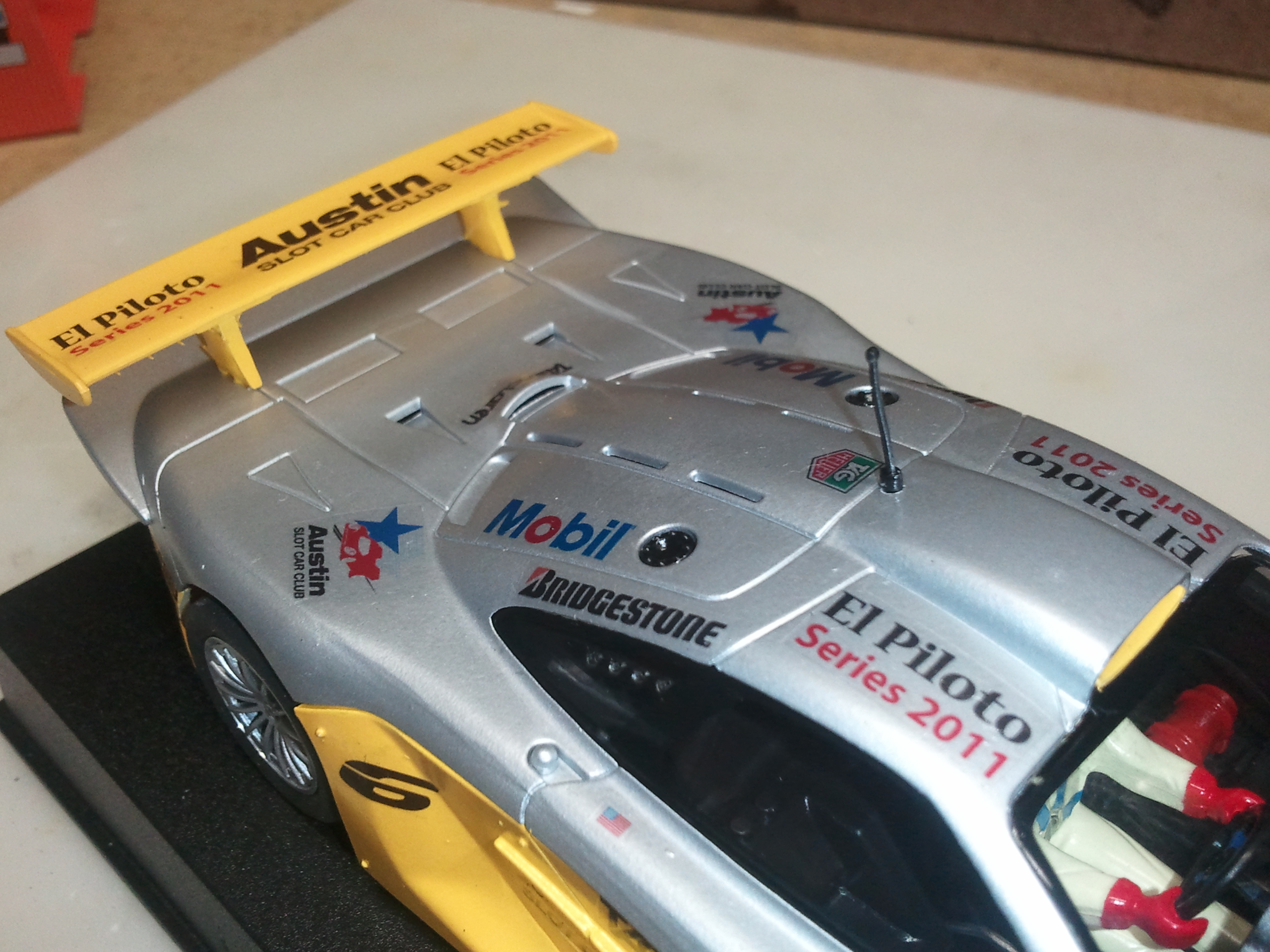
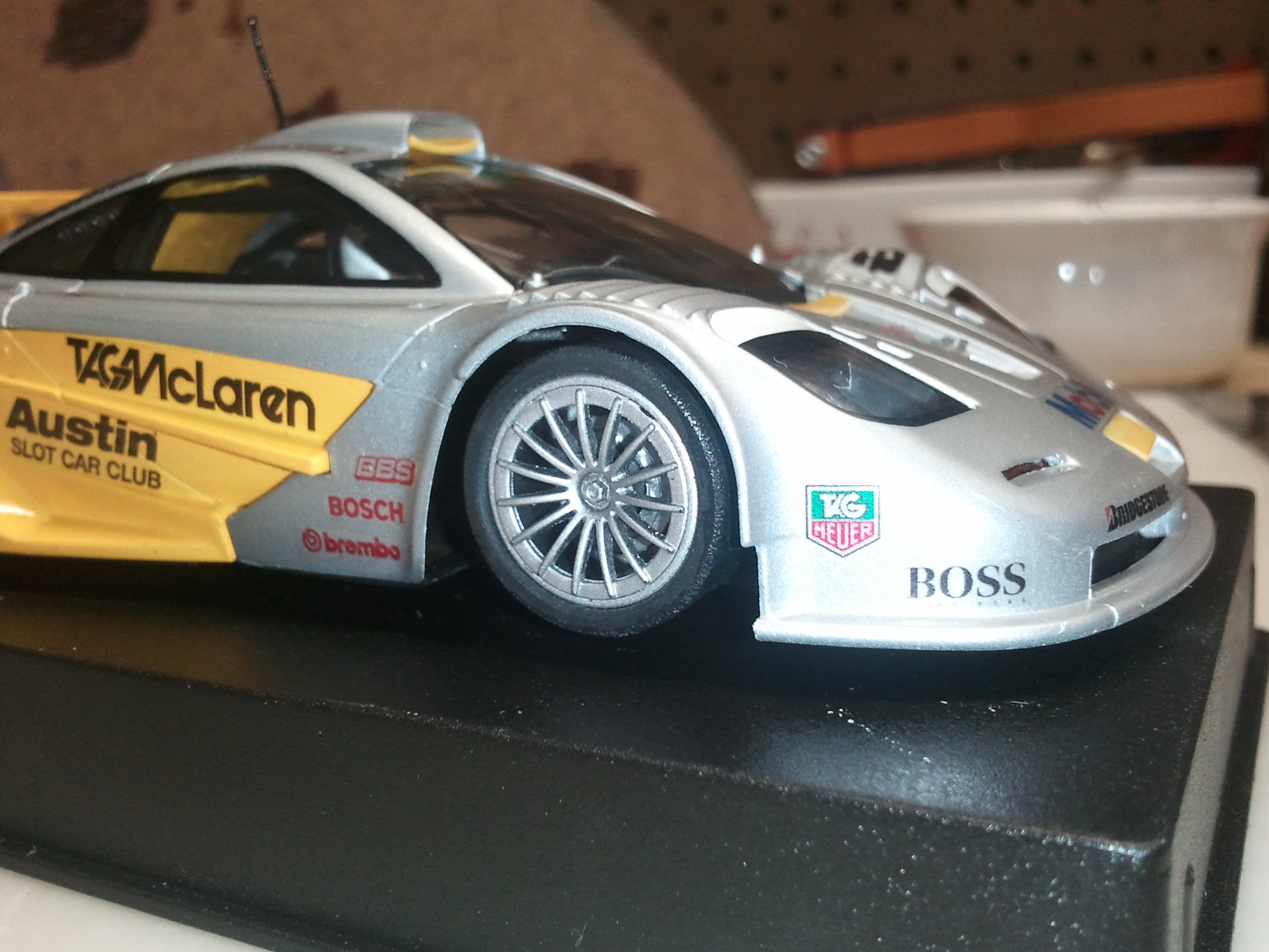
Here is how all three cars ended up looking like:
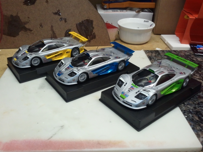
I should have chosen a lighter blue shade of paint. There is not enough contrast between the black decals and the blue paint. Nothing I can do now.
With some spare club logo decals, I add one to the base cover.

The last addition are some background graphics for the slot case. Those were done on Photoshop.

After adding some double side tape, this is the FINAL product:


I’m a lucky guy. Lucky enough to find a slot group that would help and back me up on this, and lucky enough to have an understanding wife.
_____________________________________________
Tools Used (In the order they were used):
• Philips Driver
• Machined Iron Plate (Large enough for at least one chassis)
• Assortment of magnets (I use the ones pulled from slot cars)
• Large Boiling Pan
• Baking Pan (Large enough to accommodate your iron plate)
• Oven
• Dremel Tool
• Round Gridding Tip for Dremel
• Tamiya White Primer Spray Can
• Assortment of cardboard boxes
• Variable Power Supply
• Tachometer
• Tach Wheel (You can use a 1/32 Slot.it Sidewinder gear)
• 0.035″ Hex Driver
• X-Acto Knife
• Emery Board
• Tamiya Silver Spray Paint
• Tamiya Yellow Spray Paint
• Tamiya Blue Spray Paint
• Tamiya Green Spray Paint
• 6X Cooper Braid Pieces
• Wire Brush
• Tire Truer
• Setup Block
• Clear Nail Polish (70% Nail Polish to 30% Acetone)
• 5 Minutes Epoxy
• Roll of Fiberglass Drywall Tape
• Scissors
• Tamiya Red Spray Paint
• Variable Temperature Soldering Iron
• Pinion Puller
• Pinion Press
• Cutting Wheel for Dremel
• Vector Based Software
• Clear Waterslide Decal Sheets
• High Resolution InkJet Printer
• Tamiya Clear Glossy Spray Paint
• Tweezers
_____________________________________________Did I use the word enough ENOUGH?
March 14, 2011 at 6:32 AM #1218Wow Ary! Great write-up! The cars look great and I can’t wait to “pilot” one this Thursday. 😀
Build it strong.
Keep it simple.
Make it work.
(Leroy Grumman)March 14, 2011 at 8:28 AM #1219I’m with Brian. Great writeup and work on the cars. I really wish I could participate in the event. I would love to be able to obtain one of these cars.
-Shawn
March 14, 2011 at 9:38 AM #1220Great job Ary!!!! Even a technically-challenged idiot like myself can follow your setup instructions. You have set the bar at an unbelievable height. Thank you so much for all your hard work to benefit the club.
Jim J.
March 14, 2011 at 9:52 AM #1221The part I find most humorous is that when I met Ary and showed him some of my painted cars, he told me there was no way he would do that. “I can’t paint” he said to me iirc. 😆
March 14, 2011 at 5:29 PM #1222turboman93 wrote:The part I find most humorous is that when I met Ary and showed him some of my painted cars, he told me there was no way he would do that. “I can’t paint” he said to me iirc. 😆
Shawn,
I still think I can’t paint; I’m just practicing.
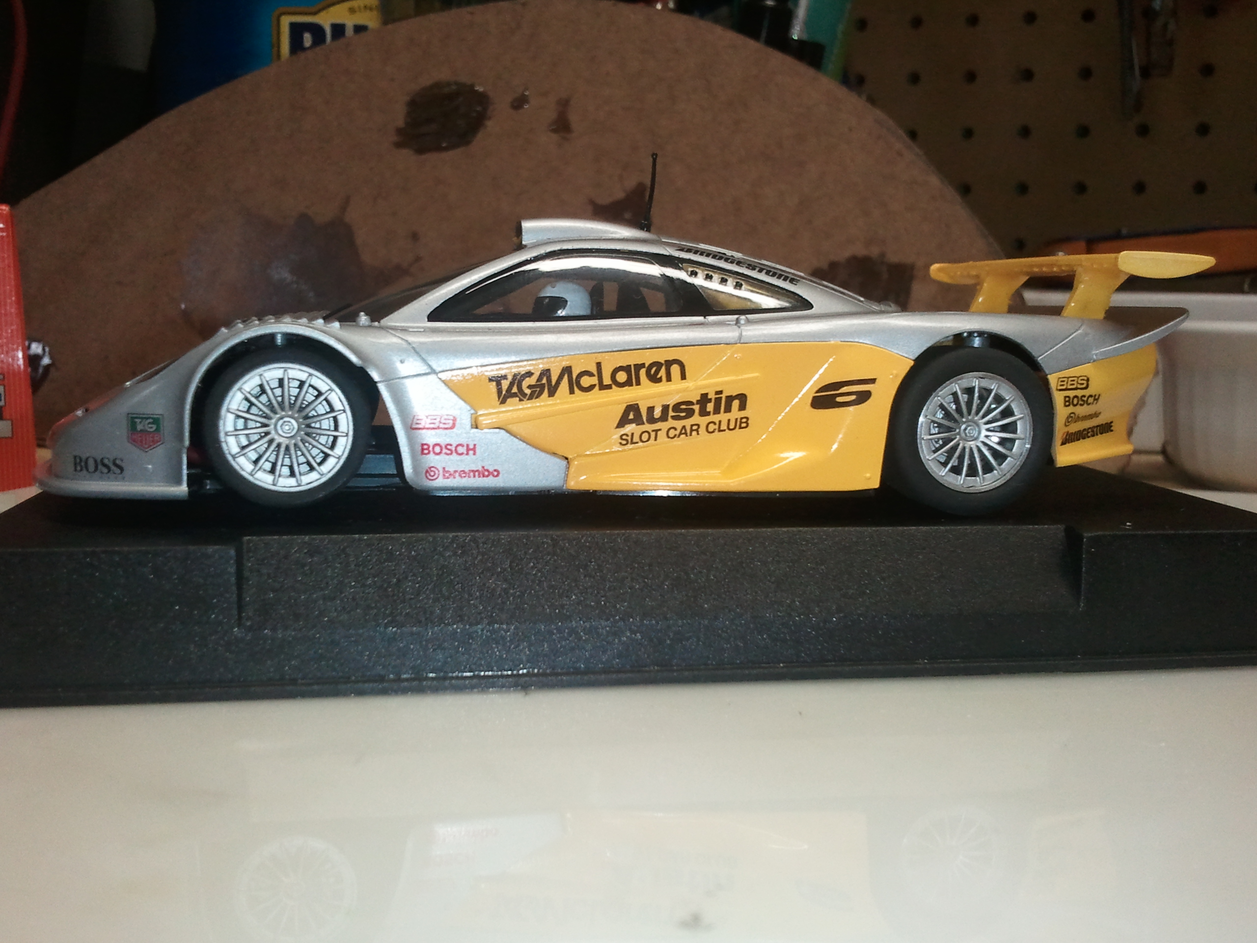
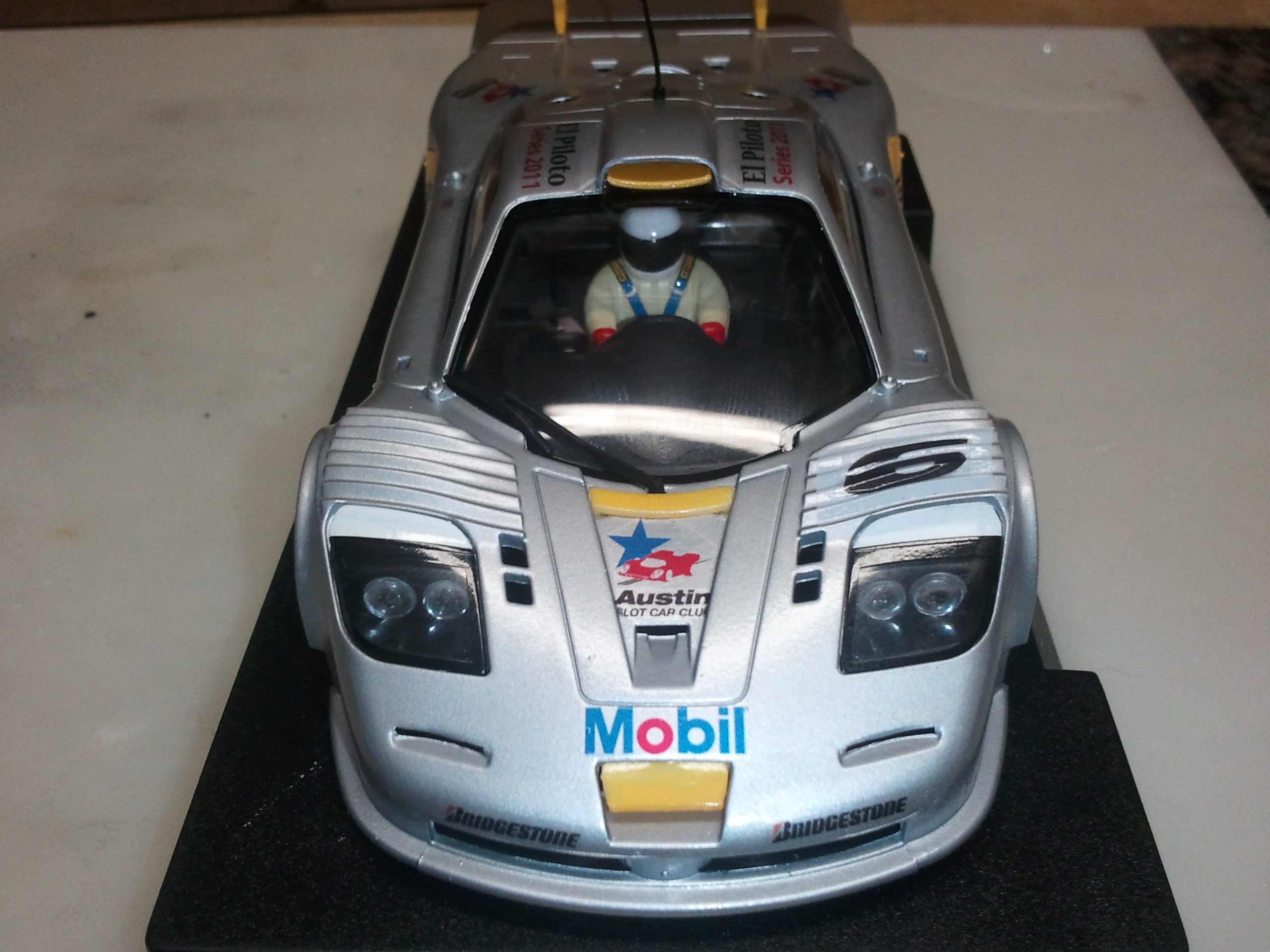
Painting the models is the only think I’m still not comfortable in doing, it was also the most stressful .. but I will try to buy the yellow lane car, that’s my favorite.Here are some close-ups:
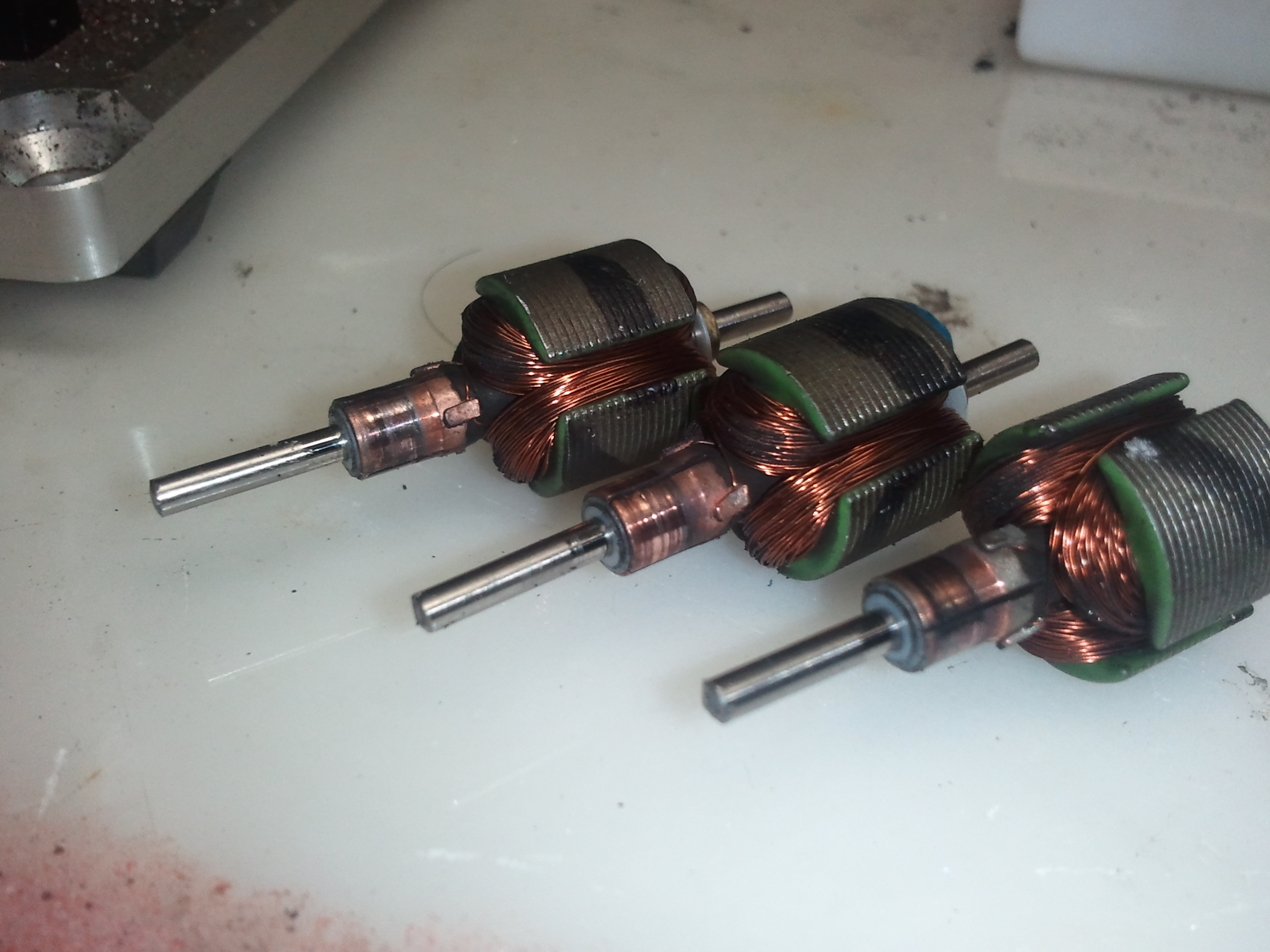
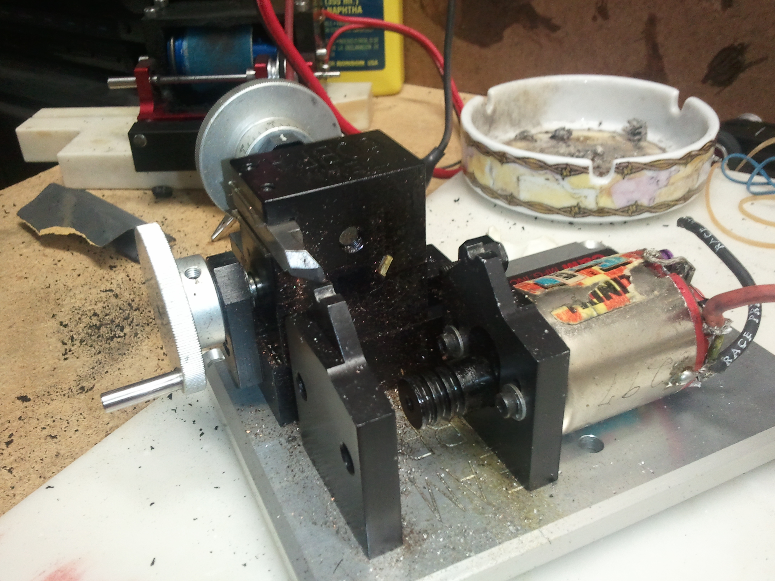
April 8, 2011 at 2:33 PM #1223Did some motor tunning Yesterday while waiting for the F1 Malaysian practice session.
I opened up the motors with the intention of sending them off to be balanced; as it turns out these motors were already balanced from factory.
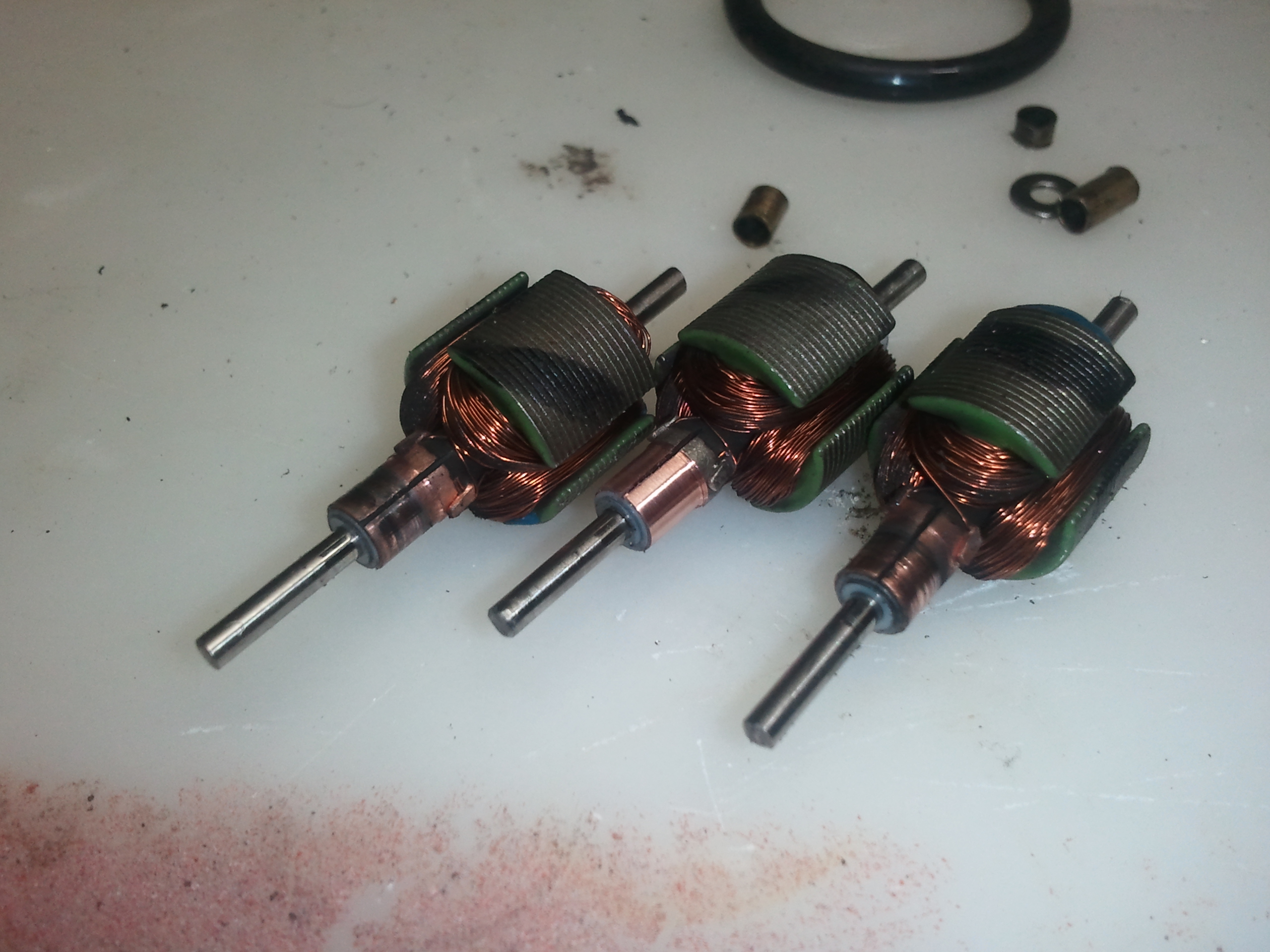
Although I don’t really think that epoxy balancing is the way to go, I decided it was pretty good already and saved some bucks.With the motors opened, I checked the commutators and, as expected, they could use some truing:
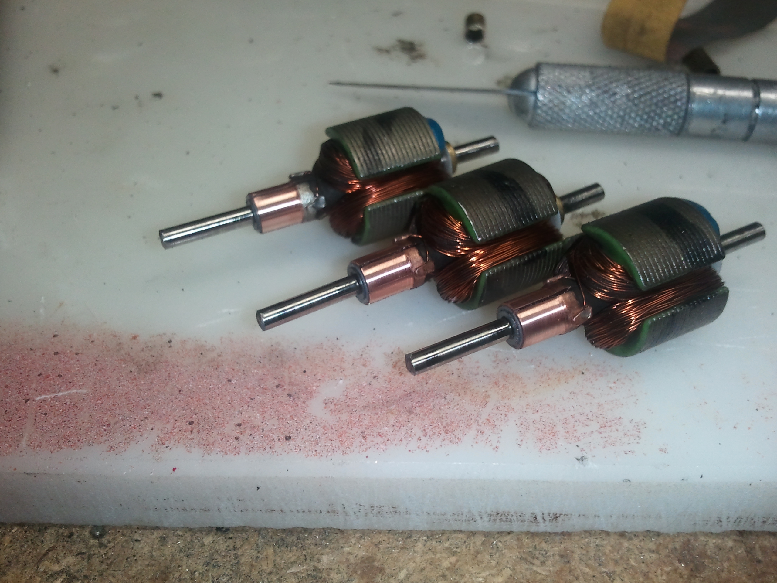
They were not extremely bad but I had to remove about .07mm from one of them.
Looking good now:
-
AuthorPosts

- You must be logged in to reply to this topic.